Tool/software: WEBENCH® Design Tools
Dear *
we want to use TPS61089 in our new design but have following questions below:
-----------------------------------------------------------------------------------------------------------
Info:
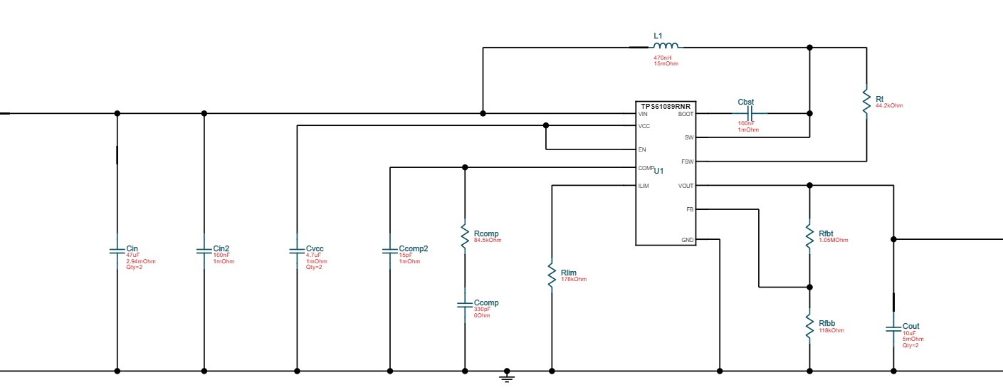
Vin 4.5 to 5V ( typ 5V)
Vout 12V
Iout max = 1.2A Iout typ from 200mA to 600mA, but can be also as low as 80mA in some cases
desired Fsw =2MHz
------------------------------------------------------------------------------------------------------------
1) i made a simulation in webench Vin=5V, Vout=12V, Iout=1.2A (CCM) (a case)
and get an eff of 90.3% and now i use the slider to set the iout to 0.3A (DCM)and the eff is 88.7% ( this is acceptable)
The webench uses 470nH 15mOhm inductor
second i made a simulation with Vin=5V, Vout=12V, Iout=0.3A (b case)
and now the simulation shows eff of 85.1% which is lower , and the inductor is 1.5uH 20mohm
so for me the first solution is better, please can you comment the negative effect of DCM mode?
2) Also in the two simulations the compensation network is different
a) case 0.3A in DCM mode. b) case 0.3A in CCM mode
So when simulating a) case only when the Iout slider is at 1.2A it is showing phase marking, when move the slider to 0.3A then we can't see phase margin?
Please can you comment the impact of the compensation network when the TPS61089 is working in DCM mode?
3)
Also for 470nH we want to use CIGW252010GLR47MNE
can we use also 1uH ( IHLP2020CZER1R0M01) with 2MHz ? Is this better than 470nH?
4)
a) how can we now form calculation after what Iout will the TPS61089 go to DCM mode
b) how can we now form calculation after what Iout will the TPS61089 go to PSM mode
c) is there any connection between PSM and DCM mode?
Best Regards,
David.