This thread has been locked.

If you have a related question, please click the "Ask a related question" button in the top right corner. The newly created question will be automatically linked to this question.

BQ34Z950: Creating Golden image file

Part Number: BQ34Z950
Other Parts Discussed in Thread: BQMTESTER

Hello!

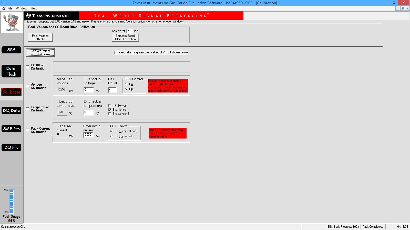
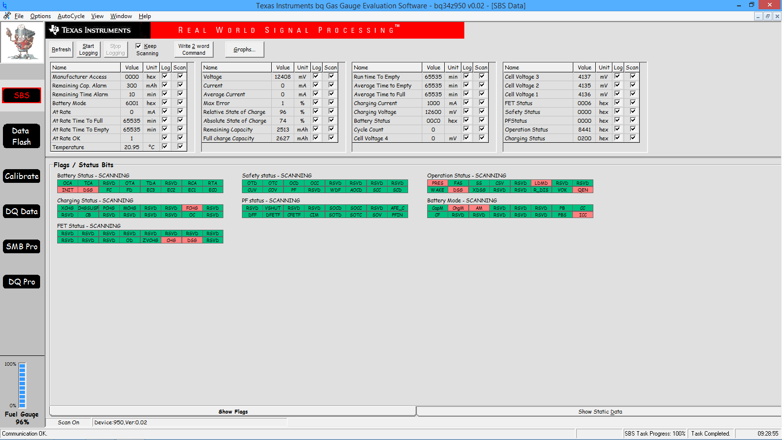
I use 3S Li-ion cells 18650 and BQ34Z950.

I successfully completed Learning Cycle (Update status 06). 

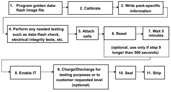
I created Golden GG file. I tried to program default .senc file and import data flash from Golden GG file. Then save this like Golden.senc through SMB Pro menu/
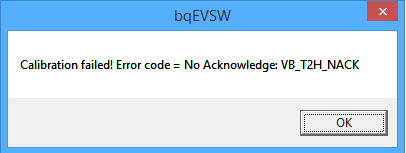
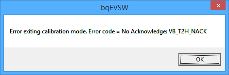
After programming this .senc file the battery does not work correctly. 
I tried to find information how to create ROM or DFI file for this IC, but neither bqTester nor BQMtester support this IC. 

Thank you in advance!
  • Hi Nikita,

    You can export the senc file from the smb pro plugin, flash memory menu, read to file option. Please explain to us what problem you are seeing? You have to enable IT once you import the senc by sending the IT enable command.

  • After programming  golden.senc file i sent reset command and then IT enable command.

    Chg and dsg bit are set. No PF. Its look like OK.

    But when I plug in the charger the current is zero. but the voltage is growing.  When I connect load bq34z950 loses connection until I connect the charger.

    Voltage of pack, voltage of every cell, temperature and so on are displayed correctly.but the current is zero anyway.

  • Hi Nikita,

    Please make sure that you don't have an accidental ground connection that causes the gauge to brownout during load.

  • I forgot to write, I tried to programm back the default senc file, configure the basic settings (such as the number of cells) and after that the charge / discharge and current indication work correctly.

  • BQ with my Golden.senc file. The charger is now connected, the voltage rises and the current is zero

  • Hi Nikita,

    Please check your calibration section. See if the cc gain and any other values there have been zeroed out. If they have, you will need to perform calibration again and then import those values or write them manually into the gauge.

  • Hello!

    The truth is somewhere near! 

    When I trying to read cc gain and cc delta an error occurs (screenshot 2).  iIn the GG file on the basis of which golden.senc is made CC Gain = 10.674

    CC Delta = 10.674, but TRM defines the range for these values 0,1 - 4 for CC Gain and 29826 - 1193046 for CC Delta.

    I tried to do CC Offset Calibration and Software Board Offset Calibration. 

    It did not help.

    Thank you for help!

    Regards, Nikita.

  • Hi Nikita,

    Please reprogram the fw for the gauge and try again. That might make calibration work.

  • Hello! 

    I tried to do as you wrote.
    1.Enter ROM Mode (Write SMB Word 00 0F00)

    2.Programm Golden.senc file.

    3. Sent SMB Command 08

    4.Rerun bq EVSW

    5. Calibrate Software Board Offset  (OK)

    6. Tried to calibrate CC Offset (Error - Screenshot 1 & 2)

    7. despite the failure in the previous point, reinserted the cells and sent a reset command (0041)

    8 Waited 5 minutes/

    9. Sent IT enable (0021)

    10 Tried to charge - voltage rises, current is zero

    CC Gain and CC Delta in Data Flash screen are still zero.

    Best regards,

    Nikita!

  • Hi Nikita,

    I don't think you are able to communicate with the gauge. Please check if you are able to read the dataRAM registers and scan them. If not, the gauge is still in ROM mode. If you are able to communicate, please send me a screenshot of the registers and an exported gg file. Your srec or send file would also help.

  • Hello!

    I apologize for  delay!

    Today I tried CC offset calibration. everything was OK, but  CC gain and  delta have not changed

     https://e2e.ti.com/cfs-file/__key/communityserver-discussions-components-files/196/gg_2600_senc.7z

  • Hi Nikita,

    Your cc gain and delta from the gg you exported are zero. Please reflash your fw.

    [Data(Calibration)]
    CC Gain = 0
    CC Delta = 0
    Ref Voltage = 1225.00
    AFE Pack Gain = 672.91
    CC Offset = -0.279
    Board Offset = -42.4
    Int Temp Offset = 0.0
    Ext1 Temp Offset = 0.0
    Ext2 Temp Offset = 0.0
    [Config(Calibration)]

  • Hello, Batt!

    I wrote above that in data flash window these values are zero and an error occurs when trying to read them (read all). so it is expected that they are also zero in the gg file.
    What does reflash mean?

    Could you describe the exact sequence of actions?

    I recall, I tried to do:
    1. flash the factory version (BR_BQ34Z950_v0_02.senc) and make the basic settings in data flash window; the gas gauge works correctly
    2. I flashed my version several times (golden.senc). without changes. the gas gaugealso does not work correctly

    Best regards!

  • Hi Nikita,

    Reflash means reprogram the fw on to the gauge. If your golden image does not work correctly, it means that the file may be corrupt or the config in it may be causing an unexpected shutdown. In either case, repeating a learning cycle can fix the problem.

  • Hello, Batt!
    Thank you!

    I will try to repeat the creation of the golden image.

    The sequence of actions is

    1) Programm default senc file.

    2)Make sure that Chem ID is right

    3) set up data flash configuration (design capacity, charge termination taper current .....)

    4)learning cycle (discharge - 5h relax- charge - 2h relax.... until update status is 06)

    5)export GG file (data flash window - read all - file -export)/ Change in GG file update status to 02 and cycle count to 0.

    6)reprogramm pack with default senc file

    7) import GG file (created at point 5)

    8) send reset command (note: after that pack worked good; problems started when I tried to make a senc file and re-flashed this file into the chip)

    9)create golden senc (smb pro window - smb wod command 00 0f00 - flash memory - read to file)

    10) production another pack (write golden senc file - calibrate - protection tests - connect the cells - IT enable + reset command(or reset +IT enable) = that`s all)

    am i right?

    Do points 1 - 9 with connected cells?

    Regards, 

    Nikita!

  • Hi Nikita,

    No.

    At step 4 you should rel-dsg-rel-chg-rel-dis-rel starting with a fully dsg battery.

    Then export your srec/senc (fw image that contains all learned data and the chem info). Your gg does not have the chem info. A gg export is just a backup option in case you know your chem ID.

    Once you have completed step 5, you have your golden pack for production.

  • Hello Batt!

    It seems to have helped.

    With one pack everything worked out.

    I am trying to make the second with a new board guided by the scheme (screenshot).

    Is it necessary to do all calibrations? in particular, the Pack current calibration bothers me - 2 A is too much for my system (2 A is the current protection fault value).

    And also I again have a problem with calibrating the CC Offset calibratoin  as I wrote earlier  (point 6)
    What should i do with this problem?
    And in order to perform tests as in point 4 (the diagram in screenshot above) I need the chg and dsg fets to be open. Do I need to do this with the reset and IT enable commands?
    Thank you for your help!

    Best regards,

    Nikita

  • Hi Nikita,

    You can calibrate the gauge with a 1A dsg. You can disable FETs with the IT enable command. Also you can use auto cc offset on init to make sure that the cc offset calibration works.

  • Hello!
    Thank you, Batt!

    Now everything works well - and 1 and 2 set.

    But there is 1 caveat - I did calibrations and tests before connecting the cells - the current was zero, and after connecting the cells the current at rest was ~ 11 mA and I had to calibrate cc offset again
    Is this normal?

    Best regards,

    Nikita.

  • Hi Nikita,

    If you have calibrated the offset out again, it should work.