A related question is a question created from another question. When the related question is created, it will be automatically linked to the original question.
If you have a related question, please click the "Ask a related question" button in the top right corner. The newly created question will be automatically linked to this question.
The LM10506 device is NRND. If you are still interested in using this device, I recommend you order a LM10506EVAL board and download the associated software for working with the EVM.
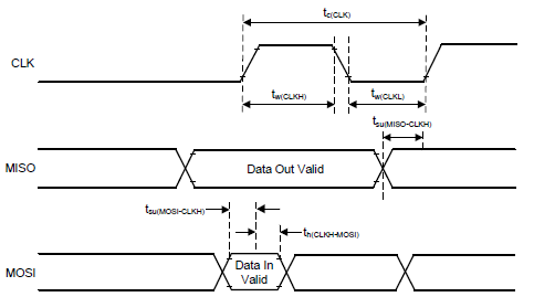
The SPI implementation is also shown in the LM10506 datasheet in Figure 23. SPI Interface Write on page 22 and Figure 24. SPI Interface Read on page 23.
CS is active-low, CLK is inactive low, data is read on the rising edge of CLK, data is transferred MSB first, and the length of address/data is 8 bits. Any additional info you require should be provided by these timing diagrams.
I apologize, but if this information cannot be found in the datasheet then I also do not have access to the device requirements for SPI timing.
The LM10506 is a legacy device targeted for SSD applications, and it is now NRND.
There are many other PMICs available with similar performance (TPS65023B, TPS652170, TPS65218D0) but most of them use I2C communication, not SPI. As you know, I2C timing specs are more rigidly defined.
I will not be able to locate the SPI Timing Requirements for the LM105xx devices in a short time period. However, below are some SPI Timing Requirements from another device with SPI interface that was released around the same time as LM105xx devices. The process should be similar, so the capabilities of the CMOS gates and drivers should be similar.
Below is a diagram that shows the definition of these requirements.
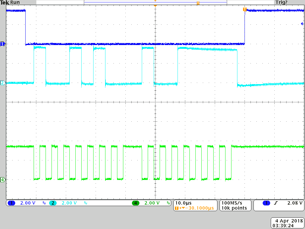
The following scope capture is from when I used the LM105xx GUI and SPI adapter to communicate with the device while I was testing a different issue (turning ON fPWM mode on all bucks).