This thread has been locked.

If you have a related question, please click the "Ask a related question" button in the top right corner. The newly created question will be automatically linked to this question.

BQ27Z561: Facing problems while configuring fuel gauge via Micro-controller

Part Number: BQ27Z561
Other Parts Discussed in Thread: BQSTUDIO, EV2400

Hi,

I have few of questions regarding programming bq27z561 using micro-controller. And for that i have stored all four files generated by bqstudio in MCU flash. My overall aim is to get accurate battery information while reading this device.

I am following a method mentioned in Appendix A of slu801.pdf to program bq27z561 via MCU.

Now,

1. For bq.fs when slave device enters in ROM mode I2C operations are performed on slave address 0x16 (0x0B on physical line) but those transactions are failing.

For example,

;--------------------------------------------------------
;Unseal device
;--------------------------------------------------------
W: AA 00 14 04
W: AA 00 72 36
W: AA 00 FF FF
W: AA 00 FF FF
X: 1000
;--------------------------------------------------------
;Go To ROM Mode
;--------------------------------------------------------
W: AA 00 00 0F
X: 1000

(Up to above stage for bq.fs MCU is writing I2C commands to slave device successfully but after device goes in ROM mode all I2C transactions are failing)

write operation in file : W: 16 05 12 00 00 10 00 07 C1 E5 66 19 67 60 67 9B 03 C1 9B FF C0

MCU is writing to slave address 0x16 with data "00 00 10 00 07 C1 E5 66 19 67 60 67 9B 03 C1 9B FF C0" on address "0x1205" (Is this operation correct?)

Can i get some explanation about format for this line : W: 16 05 12 00 00 10 00 07 C1 E5 66 19 67 60 67 9B 03 C1 9B FF C0? like 16 is slave address what is "05 12" .. and rest of the bytes ?

2. For gm.fs file when it comes to compare operation, data from gauge does not match with the gm.fs file data for some lines.

for below operation highlighted bytes are not matching with my device.

;--------------------------------------------------------
;Verify Existing Firmware Version
;--------------------------------------------------------
W: AA 3E 02 00
C: AA 3E 02 00 15 61 00 04  (data matches with my device)

Also, some of the lines in gm.fs file for comparing that does specific address is written correctly is failing.

;--------------------------------------------------------
;Data Block
;--------------------------------------------------------

W: AA 3E C0 42 AC C9 2F 1B 00 00 2F 1B D9 BB 8A 72 AA 9C 8C 74 B0 04 DB FE 28 02 B9 F4 EF 11 B7 2D B7 2D 00 00 (this operation is performed successfully)
W: AA 60 F2 24 (this operation is performed successfully)
X: 200  (after this delay)
W: AA 3E C0 42 (this operation is performed successfully)
C: AA 3E C0 42 AC C9 2F 1B 00 00 2F 1B D9 BB 8A 72 AA 9C 8C 74 B0 04 DB FE 28 02 B9 F4 EF 11 B7 2D B7 2D 00 00 (data highlighted does not match when i read 42C0 address again after above write operation on 4000 address) in this case i got read data as : b8 00 00 20 34 2e 00 20 10 00 00 00 21 00 00 00 bf 8b 00 ....


Am i missing something here? Is it necessary that all the addresses mentioned in gm.fs file must match correctly to achive accurate data for battery info?

3. Is there any sequence i have to follow for programming bq27z561? like among these four files which file should be executed first / step by step? Any prerequisites before each files?

4. Can i get some help to understand file format for .srec & df.fs file such that i can execute I2C write command on bq27z561 slave device?

Note : I am using bqstudio generated gm.fs, bq.fs, df.fs and .srec files (as attached below in zip file) using bq27z561 EVK board.

6607.Test3.zip

  • Hi 

    We will look into your question and get back to you shortly

    thanks

    Onyx

  • Hi Onyx,

    In addition to above questions, for getting accurate battery data, does it require to program all files (bq.fs, df.fs,srec and gm.fs) or only one file gm.fs will be sufficient?

    Any help regarding configuring bq27z561 via microcontroller would be appreciated!

    Thanks

    shalin.

  • "write operation in file : W: 16 05 12 00 00 10 00 07 C1 E5 66 19 67 60 67 9B 03 C1 9B FF C0"

    "MCU is writing to slave address 0x16 with data "00 00 10 00 07 C1 E5 66 19 67 60 67 9B 03 C1 9B FF C0" on address "0x1205" (Is this operation correct?)"

    No, this is not correct. 

    This command writes to I2C device (slave) address 0x16, starting at I2C register 0x05 (auto-increment). The data is 0x12 0x00 0x00 0x10 etc.

    About the .gm.fs file:

    "Am i missing something here? Is it necessary that all the addresses mentioned in gm.fs file must match correctly to achive accurate data for battery info?"

    The compare commands in the .gm.fs file will only succeed if the preceding write and delay commands are issued exactly as in the .gm.fs file. If you change anything then the gauge will likely return different data as the data that is read from the gauge is mapped from internal memory depending on the preceding commands.

    "Is there any sequence i have to follow for programming bq27z561? like among these four files which file should be executed first / step by step? Any prerequisites before each files?"

    If you want to program the bq27z561 in-system (and not with TI tools like SmartFlash) then you must implement a flash stream (.fs) parser that will execute the commands in the flash stream file (.gm.fs, .bq.fs or .df.fs) exactly.

    There is no sequence other than that you have to create a golden image and then program it to each gauge during production. The .srec can't easily be programmed in-system (it's intended for bqStudio). The .gm.fs and .df.fs files contain data memory configuration only. The .bq.fs file contains the firmware also (so it's bigger). If you use silicon that already has the same firmware revision as the one used to extract the .gm.fs file then I would just program the .gm.fs file (this file has a FW compatibility check in the first compare command and won't program if the gauge doesn't match).

    "Can i get some help to understand file format for .srec & df.fs file such that i can execute I2C write command on bq27z561 slave device?"

    The .srec has the same information content as the .bq.fs file but it's not possible to parse without additional information that isn't public. The .fs files use the flash stream format. An example parser source code is in http://www.ti.com/lit/an/slua801/slua801.pdf

  • Hi Dominik,

    Thanks for the reply!!

    So, in my device, as the firmware of silicon is matching with that of gm.fs file, it does not require flashing the other three files. Is this the correct statement?

    Also, if the above is correct, after programming gm.fs file to chip bq27 correctly gauge should give battery information accurately.

    But I am still not getting the correct battery percentage value (SOC reading from 0x2C register).

    • Does is it require any additional configuration or setting? (like design capacity, design energy, termination voltage or taper rate or these things are already there in gm.fs file?)
    • Once the gm.fs file is programmed to silicon how could it be verified that it does not require gm.fs file as it is already done. Is there any method or register from which MCU can identify not to program gm.fs file to silicon again? (because programming silicon EEPROM again and again will reduce its life)

    Thanks,

    Shalin.

  • can you please help on above questions?

  • Hello,

    The golden image (.gm.fs) is the confirmed working gauge configuration. The idea is to configure the gauge with bqStudio, the gauge EVM and the battery and verify performance with this setup (e.g. using the TI GDK).

    Once the configuration is confirmed, the golden image is exported (.gm.fs). This image contains all parameters, including Design Capacity, Design Energy, Terminate Voltage, Taper Rate etc.).

    To verify, you could read back the data memory and check if key parameters (e.g. Design Capacity) match what was in the golden image.

  • Hi

    Thanks for the reply!!

    • As per your suggestion, we have verified that generated golden image is giving correct battery soc value on BQ27z561-EVM011 EVK. So the learning cycle steps and golden image file looks correct.
    • We have programmed gm.fs file to bq27z561 via MCU over custom board and I have verified by reading all the registers back that it is same as the BQ27z561-EVM011 EVK. [ To review: please have a look at the MCU readback registers and EVK readback registers. ]

    Queries:

    1. From our initial communication we assume that if the BQ firmware version is same, then by just writing the correct gm.fs why we are not getting the correct soc readings? 
    2. Sorry to re-iterate again, Is it required to write the bq.fs file as well for getting the correct soc values even if we are getting same BQ version? [As in the EVK we are performing this steps: 1. Write the bq.fs 2. Write the gm.fs,  and we are getting the proper data with the EVK.]
    3. From looking at the documents and with our previous communication we understood that in the bare chip (with the same BQ version as EVK) we just need to write the gm.fs and we will get the correct soc data. Please correct us.

    gas_gauging_data_flash.gg.csv

  • Hi

    Is there any other step which is required to get accurate result? Or please suggest if any system readings or environment details is required for review purposes.

    I have followed the method mentioned in  http://www.ti.com/lit/an/slua801/slua801.pdf

  • If you get accurate results with bqStudio and the EVM and if you have verified that the configuration is the same on your system then the gauge will produce accurate results in the sense that the gauge will behave the same way as on the EVM.

    So if you don't get good results there seems to be still something wrong with the configuration on the system board. I typically try to hook up the TI USB I2C interface to the system board and try to use bqStudio to check if the configuration is indeed correct. If you have access to GND, SCL and SDA (and can configure your I2C host uC to disable its I2C interface temporarily) then this is the best way to verify if the gauge was truly programmed correctly.

  • Hi

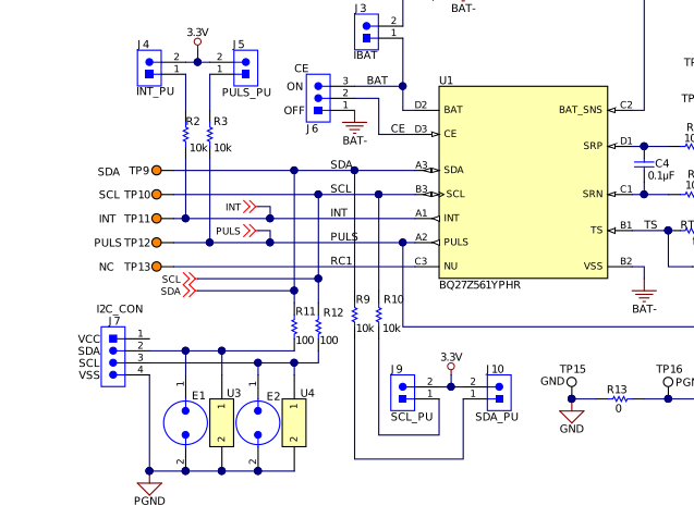
    I did setup with my system board chip to EVK board using SCL,SDA,GND I2C lines and connected with EVK board on J7 as shown in below image.

    But i was not able to read chip using bqstudio software. My system is having bq27z561 and battery connected to it, and i also disabled I2C interface between MCU and bq27z561.

    Is there any other hardware connection required so that i can read my system chip data using bqstudio?


  • If your host uC doesn't block the I2C (or issue traffic while you try to use the TI tool chain (EV2x00/GDK, bqStudio) then bqStudio should detect the gauge. You just have to connect GND, SCL and SDA. If you use a EV2400 or GDK then you don't need pull-ups on your board for SCL and SDA (these interfaces have pull-ups installed).

    J7 looks like it is directly compatible with the TI I2C cable so this looks good. Please check the voltage levels on SCL and SDA and if possible capture the traffic on SCL and SDA with a scope when you start bqStudio.