This thread has been locked.

If you have a related question, please click the "Ask a related question" button in the top right corner. The newly created question will be automatically linked to this question.

BQ76940: BQ76940 NTC related question

Part Number: BQ76940

Hi team,

i met an interesting problem of BQ76940 in 12s battery and would like to get your help. 

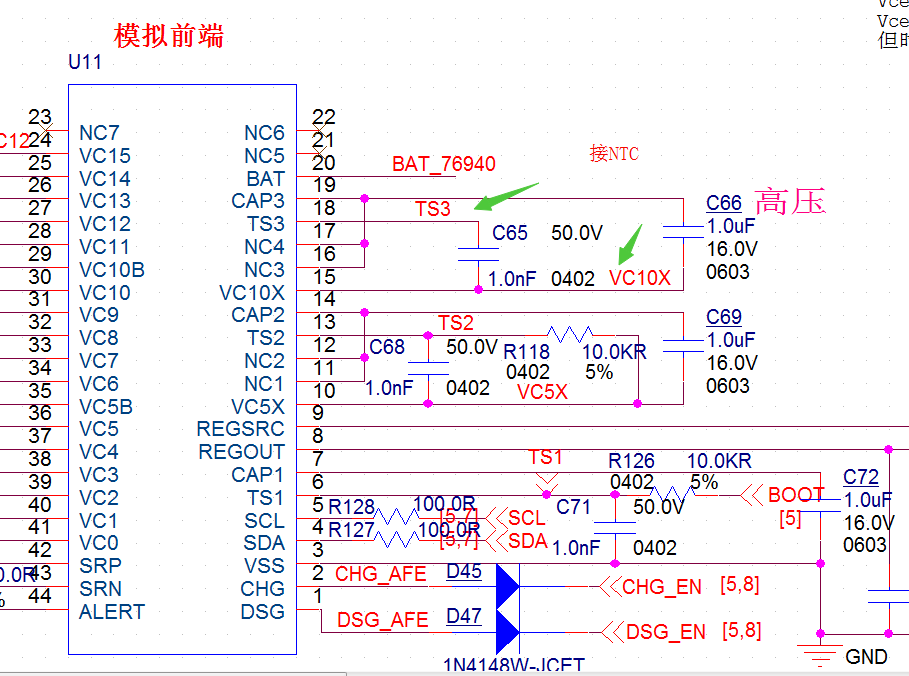
Firstly, i used an resister divider(4.7kohm) board as 12s battery cell. But i found the sampled cell voltage is not stable when i turn on NTC function(TEMP_SEL). When i turn off NTC, the sampled cell voltage is stable. 

Then i tried to change the divider resister to 1kohm, i found the sampled cell votlage is still not stable, but getting better when i turn on NTC. 

Then i tried to use actual battery cell, i found the sampled cell votlage is stable when i turn on NTC. 

Do you have any comments for this phenomenon? Does the NTC feature consume a lot of current?

  • Hi Hollis,

    The EVM uses 200 ohm resistors for the cell simulator resistor divider and the TS1 pin is only connected to Cell 1 when the BOOT button is pressed. On your board, is the TS1 pin always connected to Cell1? If so, this might be causing current draw through the filter resistors.

    Best regards,

    Matt

  • Hi Matt, 

    No. Customer only use TS3. TS1 and TS2 are grounded with 10kohm resistor.

    Does the NTC feature consume a lot of current when it is enabled?

    what's the recommended sch if customer wants to use 1 NTC here. 

  • Hi Hollis,

    Temperature measurements are taken every 2 seconds. The load on the supply pins can vary by +/- 165 uA = 3.3V/(10k + 10k) nominal at room temperature. 

    The recommended schematic for the temp sensor is to follow datasheet figure 14. However, a small filter capacitor can also be used in parallel (see TI Reference Designs for exampes). The capacitor should not be used if there is no external temp sensor - it can cause issues with device start-up.

    Best regards,

    Matt