This thread has been locked.

If you have a related question, please click the "Ask a related question" button in the top right corner. The newly created question will be automatically linked to this question.

TPS2121: TPS2121 output drop when switching

Part Number: TPS2121

I have two input,all is 5V.

IN1:5V_DC

IN2:5V_USB

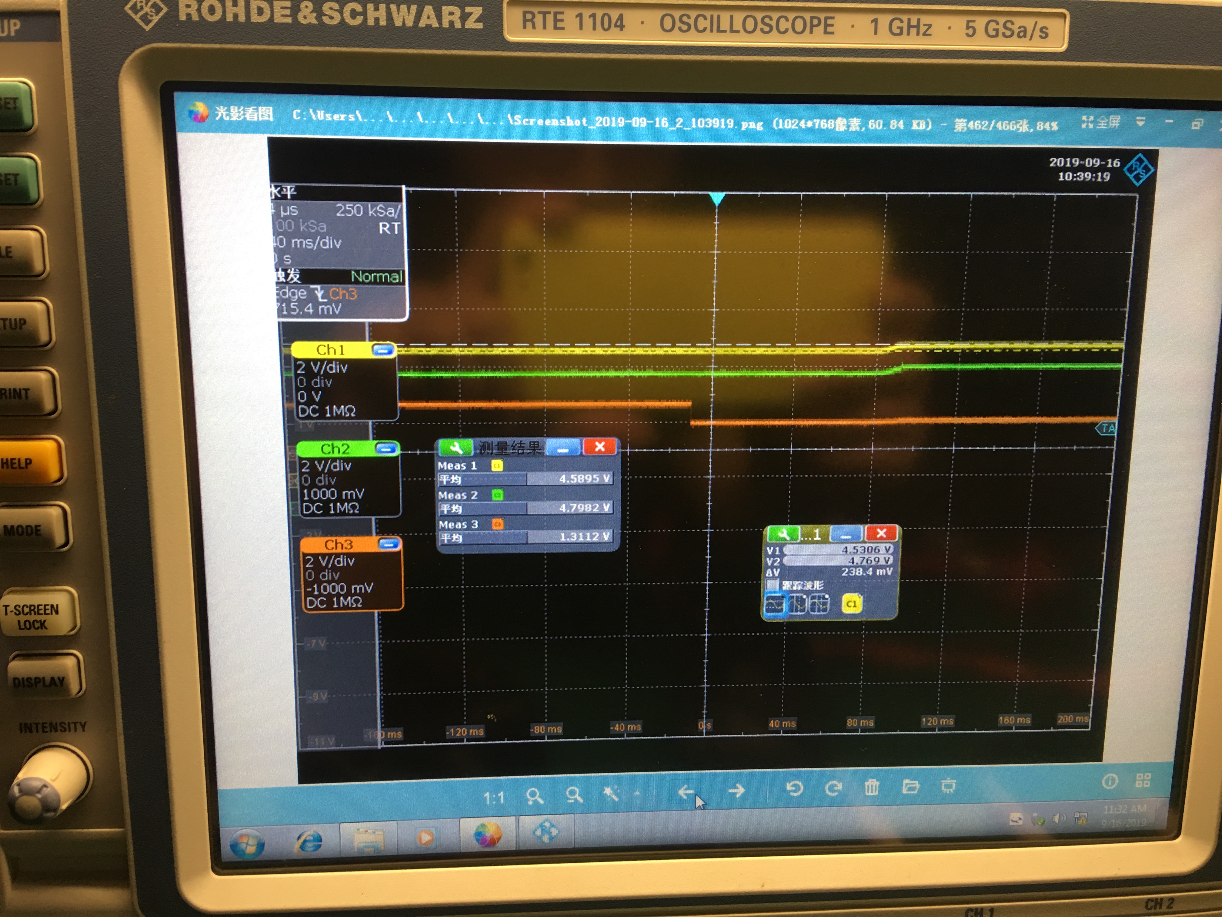
When 5V_DC pulls out and 5V_USB keeps,the output volotage will drop 

And I Test the ST pin,but this pin still low volotage,didn't change

I also find that the output volotage will be 4.2V in IN1,when resistor load is 5R.

Is there something wrong with the output volotage?

Could you tell me the reason? 0488.TPS2121_XCOMP.pdf

  • I pull ST up to RP1,and output volotage drop reduce 。

    But it still makes output volotage drop to 3V in 440us。

    How can i reduce output volotage drop?keep output volotage over 4V

     4721.TPS2121_XCOMP.pdf

  • Hi Weifeng,

    Your schematic does not seem to line up with your scope shots. If you have 5V on IN1, the the voltage on PR1 will be 5*5.1/(5.1+4.7) = 2.602V.

    If you have 5V on IN2, the voltage on CP2 should be 5*5.1/(5.1+10) = 1.688V

    Since it seems to be that you are using this device in XCOMP mode, the voltage on PR1 is larger than the voltage on CP2 which means the priority is set to IN1 over IN2. So if IN2(5V_DC) is pulled out, this should not have any change to the device. No channel flip should occur. Channel 1 will continue to pass voltage to the output. 

    I am not sure I understand your question.

  • Hi ,Shreyas Dmello

    The priority is set to IN1 over IN2

    But when the IN1 pull out,the output volotage drop,the minimum output voltage is 3V

    How can i reduce output volotage drop?keep inimum output voltage over 4V

  • Hi ,Shreyas Dmello

    The priority is set to IN1 over IN2.

    But when the IN1 pull out,the output volotage drop,like the picture

    The output volotage will drop to 3V,which makes the system reset

    I want to reduce the output volotage drop,and keep  minimum output voltage over 4V 

  • My purpose is when IN1 pull out,the IN2 can power to the system without volotage 

    But it seems to be that no matter how I debug it there's still a voltage drop

    Please help me to check the schematic

    Thanks

  • HI Shreyas Dmello,

    Do you have any other contact information?

    I am in China.We have time difference

    It's one o 'clock in the morning in China

  • Hi Wiefeng,

    IN1 is the 5V_USB not the 5V_DC correct? This makes a little more sense. When IN1 is pulled out, the switchover will only be triggered when PR1<CP2 This means that the voltage on PR1 will have to drop lower than 1.688V for the switchover to take place and that looks like why the output drops a lot. I would suggest either changing the PR1 voltage divider or the CP2 divider to make sure that the switchover happens as fast soon as possible. 

    For example: If the voltage divider on PR1 was set so that the voltage when IN1 is connected was around 1.8V, IN1 would still have priority over IN2. When IN1 is removed, switchover would trigger sooner which would then reduce the output droop. 

  • HI Shreyas Dmello,

    You are right. IN1 is 5V_USB

    I understand what you said,but do you have any other solution?

    and are there any problems with my schematic design ?

    Thanks

  • Hi Weifeng,

    You have to trigger the switchover at the right time to minimize output drop. To do so you will have to change the resistor network either on PR1 or CP2 as stated before.

    As far as the rest of the schematic goes;

    1. Your OV is set to 6V. Is this okay for your system?

    2. The ILIM is set to 4.94A. Is your system okay with such a high current limit?

  • Hi Shreyas Dmello

    I did the test the way you said.

    I find if i change the voltage on CP2 to 2.4V or 2.0V and  the voltage on RP1 is still 2.66V ,the priority of IN2 is over IN1.

    At the same time,i test the volotage on RP1,and i find the volotage on RP1 become 1.4V. 

    I don't know why the volotage on RP1 will change from 2.66V to 1.4V. 

    Thanks

  • Hi Weifeng,

    Could you please take a scopeshot during this "event"?

    It would be helpful to have PR1, CP2, ST and VOUT in this scopeshot.

    By the way, do you have a TPS2121EVM? 

  • Hi Shreyas Dmello

    I'm sorry I'm off duty. I can't use the oscilloscope.

    And i don‘t have the TPS2121EVM

    Is there a requirement for the difference between the volotage on RP1 and CP2?

    From the test,i find that if RP1-CP2>1V, the priority of IC is correct.

    And the ST pin must pull up to RP1? 

    I find that the ST pin connect to GND from TPS2121 datasheet. Is right?

  • HI Shreyas Dmello,

    I did the test the way you said.

    I find if i change the voltage on CP2 to 2.4V or 2.0V and  the voltage on RP1 is still 2.66V ,the priority of IN2 is over IN1.

    At the same time,i test the volotage on RP1,and i find the volotage on RP1 become 1.4V. 

    I don't know why the volotage on RP1 will change from 2.66V to 1.4V. 

    Thanks

  • Hi Weifeng,

    Please share it when you can. No rush. 

    ST can be grounded if unused but it is an open drain output. Some implementations pull up to the PR1 voltage, some implementations pull up to V_out, some implementations pull up to an external compliant voltage source (check the datasheet for max voltage allowed on this pin). But it basically a channel flag. If pulled up to a compliant voltage, when the voltage is high it means channel 1 is enabled, and when the voltage is pulled low, it means channel 2 is enabled. It is a very useful tool.

  • HI Shreyas Dmello,

    But could you tell me the reason

    "

    I find if i change the voltage on CP2 to 2.4V or 2.0V and  the voltage on RP1 is still 2.66V ,the priority of IN2 is over IN1.

    At the same time,i test the volotage on RP1,and i find the volotage on RP1 become 1.4V. 

    I don't know why the volotage on RP1 will change from 2.66V to 1.4V. 

  • Hi Wiefeng,

    In this situation CP2 is at 2.4V and PR1 is now at 1.4V so CP2 will have priority which makes sense.

    Unfortunately, the question is why is PR1's voltage dropping. This is why I want to take a look at the scopeshots and see the behavior.

  • Hi,Shreyas Dmello

    I tested the RPI,IN1 and Vout with the oscilloscope.

    The test results are shown in the picture. IN1 and IN2 exist together

    CH1:Vout

    CH2:IN1

    CH3:RP1

    If only IN1 is used,the RP1's volotage will be normal,about 1.8V

    But if IN1 and IN2 exist together,the RP1's volotage will be change from 1.8V to 1.0V

  • Hi Weifeng,

    In that scopeshot not only does it look like PR1 is dropping when IN1 is stable, it also shows IN1 rising with VOUT after the switchover I presume. This could be because of no current being pulled from this source now which makes sense.

    I am looking into the PR1 drop. This is not expected behavior. What is CP2 in this case? Or IN2? I would say that something is off with your setup because it looks like PR1 is being externally pulled down!

  • Hi Shreyas Dmello

    So now how do I solve this problem?

    Could you give a reference design that meets the my requirements?Then I printed a PCB according to the reference design and came back to test

    Becsuse i don't have a demo borad of tps2121

    Thanks

  • Hi Weifeng,

    You can find TI's reference design on the EVM here: http://www.ti.com/tool/TPS2121EVM-023

    The user guide describes the circuit configuration for 12V inputs, 8V inputs and 5V inputs. You can find the guide here: http://www.ti.com/lit/ug/slvubd2a/slvubd2a.pdf

    My base recommendations are as follows:

     1. Use ST as a method of feedback.

     2. Make sure your supplies are not a limiting factor in terms of current supply

     3. Use IN1 for your priority supply 

     4. Make sure your soft start is not longer than it needs to be.

     5. Make sure you have enough hysteresis between PR1 and CP2 so that the device does not bounce between the two inputs when power is drawn from either source

     6. Have input capacitance to protect the supply during inrush and an output capacitor to minimize output voltage dip 

    If you are still having issues, I would recommend posting a new E2E question.