This thread has been locked.

If you have a related question, please click the "Ask a related question" button in the top right corner. The newly created question will be automatically linked to this question.

LM3671MF-3.3 HIGH LEAKAGE CURRENT DURING SHUTDOWN

Other Parts Discussed in Thread: LM3671

First, I find it very frustrating when someone designs a web tool that does not allow an exception when it doesn't work. I tried to put the part number in the part number field but the filed does not recognize it and will not allow a more generic description.  It will allow "LM3671MF-" but stops me when I type a 3.  It only offers a 1.8 or 1.2  So my only option is... "no part number"  So I am not going to spend too much time describing my problem until I know this can be seen by forum members.

I have have had five proto boards built,  all with LM3671MF-3.3 IC's on them.  I have three power rails 5V, and 20V, both behind the LM3671, sourcing 3.3V.  Everything comes up fine.  But when I take the enable pin low, I still have 300uV @ various voltages of between 600-800mV depending on the board. being sourced by the LM3671.

I am building a battery operated device and chose the LM3671 because of the specified .01uA standby current.

Am reading the data sheet wrong?

800uA seems kinda high for a device that's supposed to work with a single cell battery

Is it possible I got hold of a bad batch?

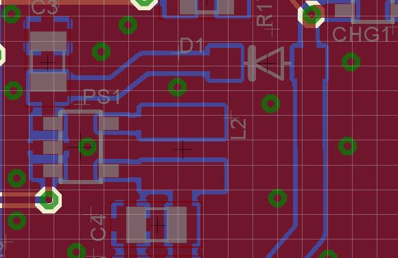
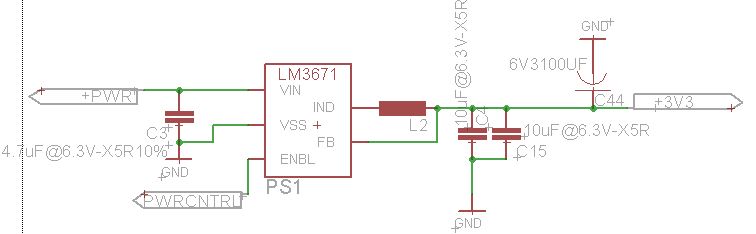
I can supply drawing and layout once I know this post is going to be read.

Thanks,

  • Hello John,

    I am not quite sure to understand what you mean when you write : " I still have 300uV @ various voltages of between 600-800mV depending on the board"

    Could you elaborate here?

    You understood the datasheet right.

    As well, to better help you could you provide schematics and layout?

    Thank you very much for reaching out to us!

    Best Regards,
    Dorian

  • Dorian,
    Thanks for your reply.

    All LM3671 Regs on all boards tested source  ~300uA when I attach a VOM on the reg output to gnd while the enable pin is zero volts. But the voltage on each board was different.
    RE: Datasheets:  I've been working with switchers for 10 years.  But there is always a new opportunity for confusion.


  • Hello John,

    What is the voltage applied to PWR node?

    Why do you need such a large cap (3100uF) at the output of your system?

    How do you measure this 300uA current flowing in your system's output? Are you using a current probe?

    In shutdown mode, PFET and NFET stop switching. Standby current is specified .01uA at the input.

    Thanks,

    Dorian

  • Morning Dorian, Thanks for your help.

    What is the voltage applied to PWR node? 3.7-4.5V (Li-ion battery)

    Why do you need such a large cap (3100uF) at the output of your system? To minimize voltage fluctuations during changes in current draw.
    Does a large capacitor affect how much current the regulator sources while it is off?

    How do you measure this 300uA current flowing in your system's output? Are you using a current probe? I used a VOM amp meter. measuring from 3.3V rail to ground.  
    It is probably sourcing more form leakage into all the components sitting on the rail.  I did not bother to do an in line test because it would only show more current flowing than specified.

    In shutdown mode, PFET and NFET stop switching. Standby current is specified .01uA at the input. Interesting
    Can the LM3671 source 300uA or more without also flowing into the input?

  • Hello John,

    "Does a large capacitor affect how much current the regulator sources while it is off?"

    It certainly could affect the discharge of your output stage when device is in shutdown. 

    Could you share with us waveforms of the SW voltage node and output voltage and output current waveform when the device enters shutdown? 

    This can help me understand why you are observing  between 600-800mV at certain nodes. 

    Did you make sure you could measure 0.01uA shutdown currenn at the input ?

    "Can the LM3671 source 300uA or more without also flowing into the input?"

    There could be if VIN is lower than VOUT.

    Thank you very much!

    Best Regards,

    Dorian

  • Hi Dorian,

    RE: Waveforms during shutdown.
    There is no waveform during shutdown.  It is a flat line.  With no fluctuation is voltage there is no fluctuation in current, so a picture of a flat line is of little value.
    Could I have gotten a bad batch of IC's?
    Could the board shop have over cooked them? Although I doubt the IC's was over cooked, everything else works and I have used this board shop for years with no issues.

    Thanks

    John K.

  • Hello John,

    You mentioned earlier you were observing various voltages of between 600-800mV on your boards, when you enter shutdown then there is discharge of your output stage, that's what I would like to see. I cannot really help if you don't provide data here. 

    Have you tried to do the same tests without the big capacitor at the output?

    "Although I doubt the IC's was over cooked, everything else works and I have used this board shop for years with no issues."

    I don't know the history here. Did you discover this issue on fresh boards? Performances you haven't seen on former boards?

    According to you, could this have been in your system for years?

    Thank you very much!

    Best Regards,
    Dorian

  • Hello John,

    I haven't heard back from you.

    Do you have any update on the previous questions?

    Thanks,


    Dorian 

  • Dorian,
    Sorry for the delay.
    I found the problem.
    As I mentioned previously, this is a beta board using a ESP32 from Espressif with many new capabilities that I have never tested.  I implemented a feature to monitor battery voltage using the internal ADC of the CPU.
    I used a simple resistor based voltage divider to bring the monitored voltage within range of the ADC Vref.
    What I did not realize was that the ESP32 allows the simple resistor network to backfeed voltage into the ADC and out the VDD pin of the ESP32.
    I found this out after  hand soldering a LM3671 with its components on a bare board.
    It worked as expected, which caused me to look for other causes.
    I did not think to look for the resistor issue until I proved to myself it was not the LM3671.

    With 20/20 hindsight, I should have removed the diode in front of the LM3671, this would have also shown that the power was not coming into the LM3671.
    Anyway, thank you for your persistence and patience.