Because of the Thanksgiving holiday in the U.S., TI E2E™ design support forum responses may be delayed from November 25 through December 2. Thank you for your patience.

This thread has been locked.

If you have a related question, please click the "Ask a related question" button in the top right corner. The newly created question will be automatically linked to this question.

TL431: TL431 reference design: Efficient 5-V Precision Regulator

Part Number: TL431

Hi,

i have a question about TL431, in the reference design Efficient 5-V Precision Regulator,

what is the function of the triode in the circuit?

BTW, what is the difference between Efficient 5-V Precision Regulator and shunt regulator?

I consider both of them can regulate the voltage.

Thanks.

Best regards

Mason

  • Hi Mason,

    I assume you're talking about the BJT, correct? 

    Also, while they are both voltage regulators, the shunt regulator is usually used for light loads vs a linear regulator application which is more applicable at heavy loads. Just view these as a linear regulator and shunt regulator and then the differences become obvious, they each have their pros and cons.

    Thanks,

    Abhinav.

  • Hi Abhinav,

    Thanks a lot for you help.

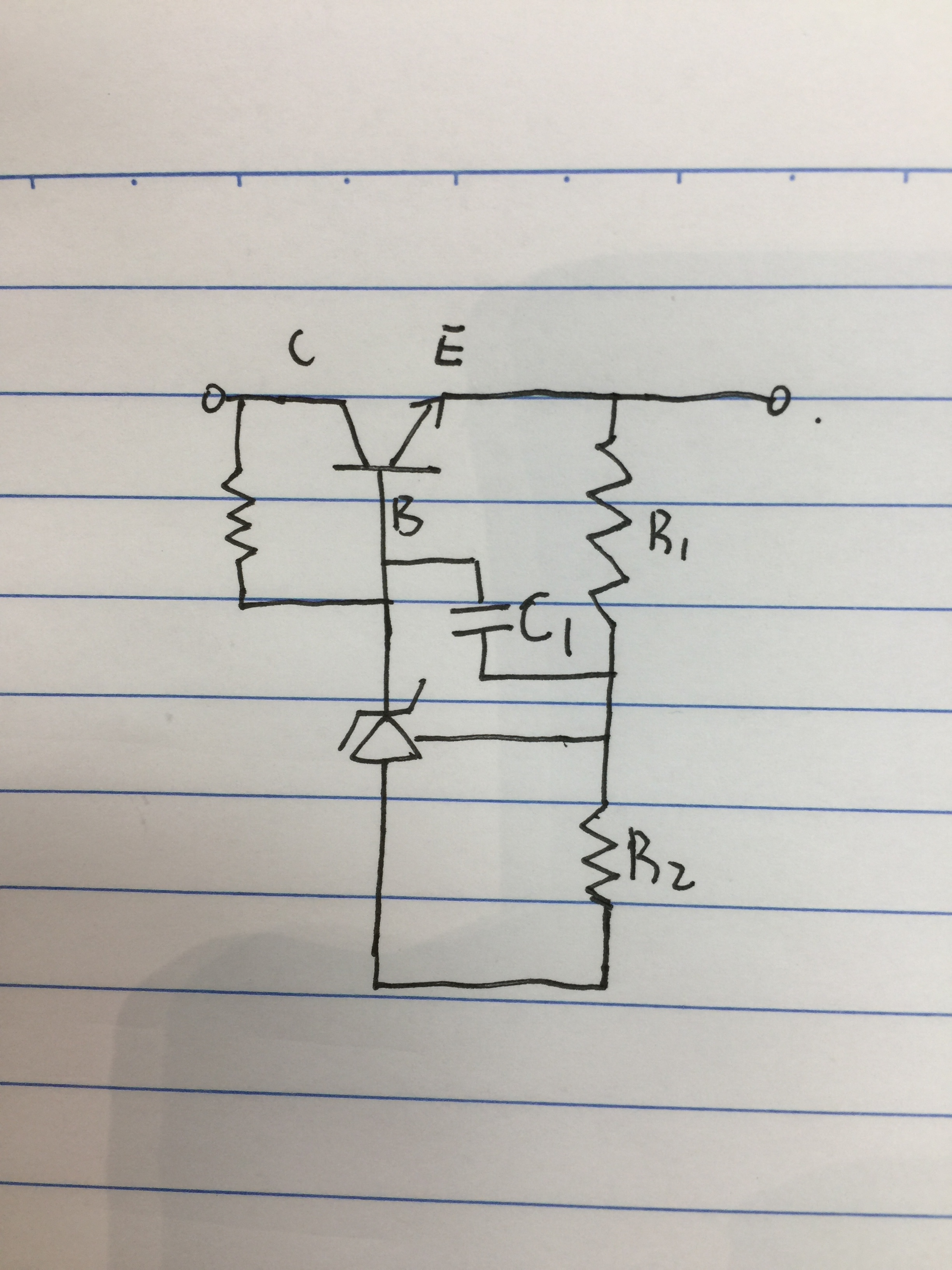
    i still have a question, image shown below:

    What is C1 usage in this circuit? I thought it maybe can eliminate self-oscillation, but i don't know the reason, can you teach me or show me some material to learn? 

    Thanks a lot.

    Best regards

    Mason

  • Hi Mason,

    The TL431 drives the load off of the emitter of an NPN transistor in “common collector” or "emitter follower" because the voltage gain from base to emitter is nearly unity.
    The critical characteristic of the emitter follower is that it is very wide-band and does not introduce low-frequency poles into the loop gain. This has to do with the output impedance of the emitter follower. This makes compensation very easy which is by adding a “dominant pole” compensation by putting a pole into the loop created by the capacitor around the TL431. In this circuit the C1 adds a low frequency pole that makes the circuit be stable regardless of input and output capacitor. Without the C1 there will be conditions where the input and output capacitors might cause oscillation.

    Try the collateral below for more information. The TL431 is a vref + error amplifier in one device solution so you can assume it will follow the same requirements as the document below. If you are using the TL431, I would suggest to use the TL431LI due to its better performance across temperature. Check the links on the signature for TL431LI information.

    www.ti.com/.../snva020b.pdf


    -Marcoo