Other Parts Discussed in Thread: TINA-TI,
Dear Sir,
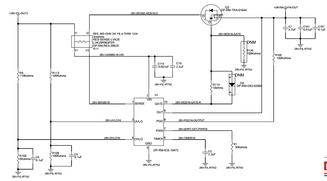
We have used LM5069MM-2/NOPB for OV/UV & Over-current protection IC and need some clarifications on this.
Following are the values chosen in the Circuit;
Rsense = 3 milliohm
Undervoltage threshold = 5V
Overvoltage Threshold = 57.5V
Resistor at PWR pin 30Kohm
Capacitor at TIMER pin = 2.2 uF
Vin Max = 28V
Test Conducted: Short Circuit (Applied Input Voltage to IC = 28V / 18A)
1. For the chosen Rsense value (3milliohm), IC will shutoff the MOSFET only at 18.33A (55mV at Rsense) & ensured conduction upto 16.16A (48.5mV at Rsense).
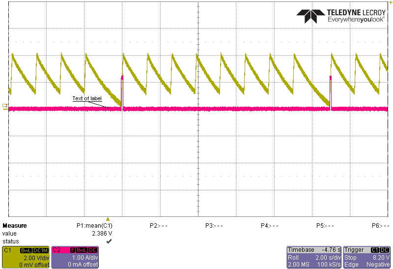
But in our observed case, only 3A current is allowed during fault timeout period of 103ms. Observed load current graph is attached here. (second picture)
2. As per the restart sequence graph given in the LM5609 datasheet (page no: 16), if the fault persist after fault timeout period then the IC keeps the MOSFET in OFF condition for the calculated restart time (19.85 seconds).
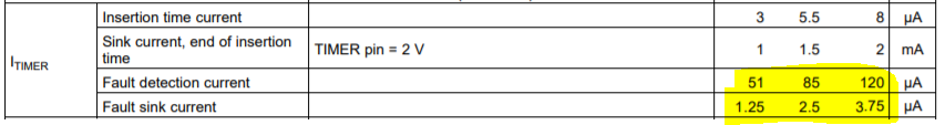
| Capacitor Discharging time after fault timeout period (seconds) | 2.2uF*2.75V/2.5uA | 2.42 |
| Total Seven cycle charging time(Seconds) | 7*2.2uF*2.75V/85uA | 0.4982352941 |
| Total Seven cycle discharging time (Seconds) | 7*2.2uF*2.75V/2.5uA | 16.94 |
| Total restart time (Seconds) | 19.8582352941 |
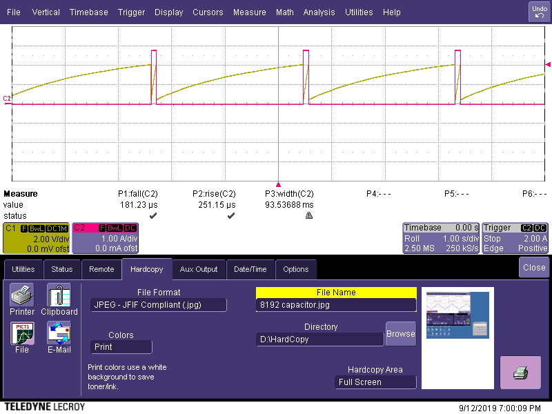
But in our case, restart time of only 2.75 seconds is observed. Also seven cycles of timing capacitor charging & discharging is not observed, only one cycle exist between the two fault timeout period. Observed load Current & Timing capacitor voltage graph is attached here (Iload-Vtimer.jpeg).
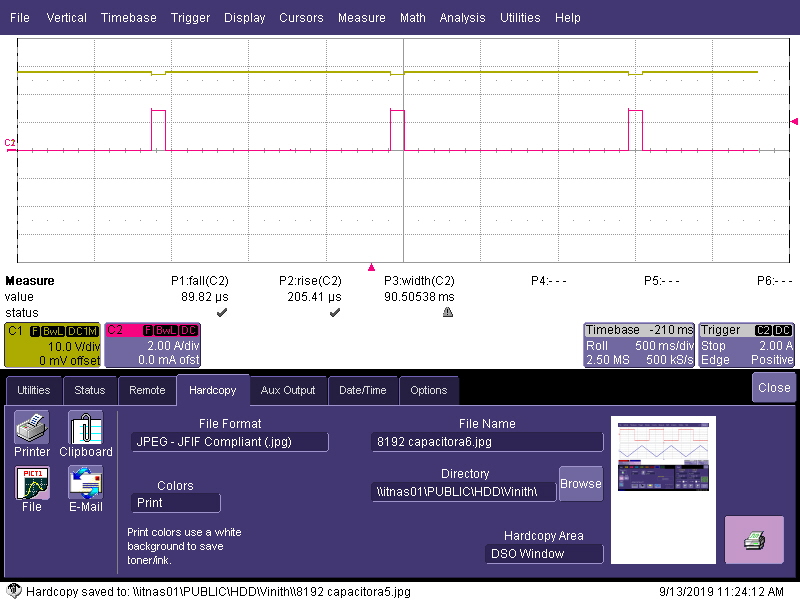
3. Restart time of 1.45 seconds is observed while probing load current & MOSFET Vds. Why is this two different restart time is observed while probing one case MOSFET Vds & load current and other case Timing capacitor voltage& load current. Observed result is attached here ( 1st & 2nd picture).
Kindly clarify the above mentioned points.
Awaiting for your reply.
Thank you