Other Parts Discussed in Thread: TIDA-00377, , TINA-TI, TIDA-00751
Dear Team
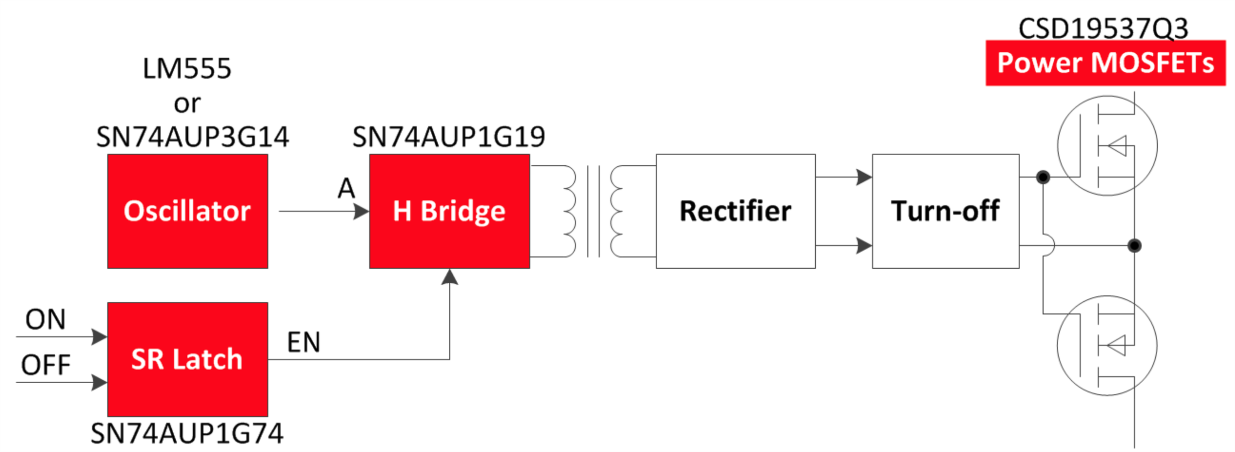
http://www.ti.com/lit/df/tidrjj8/tidrjj8.pdf
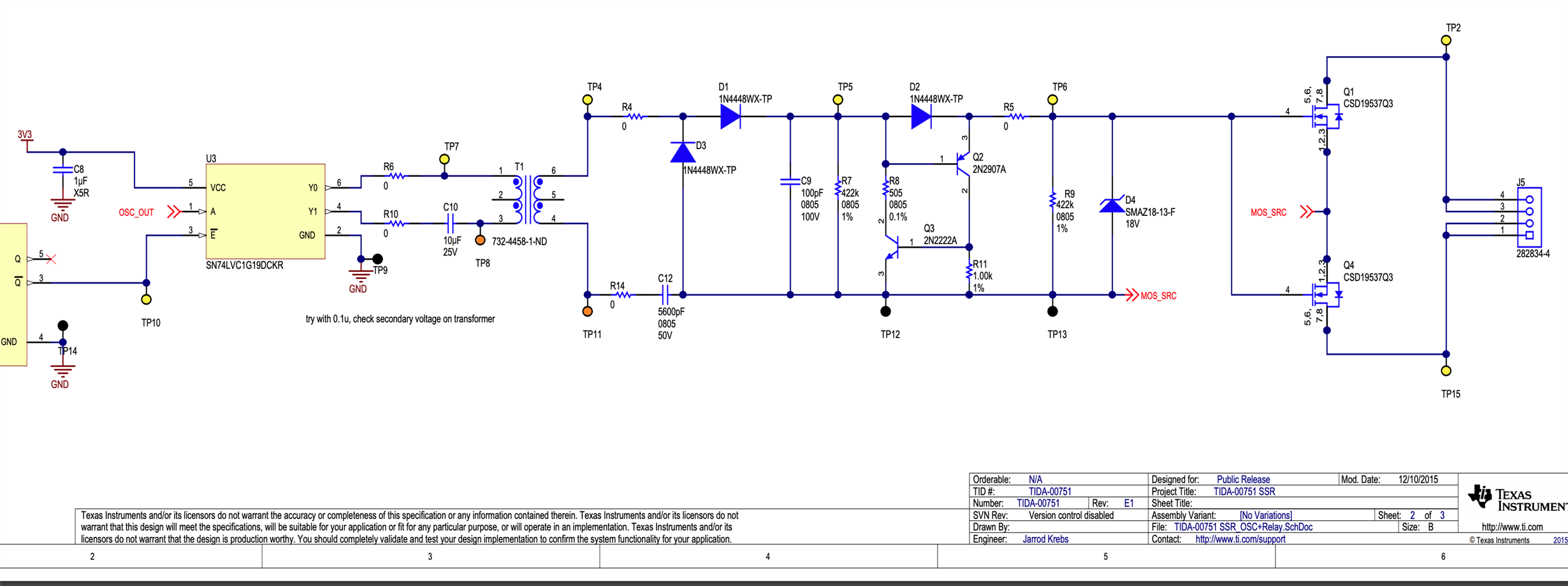
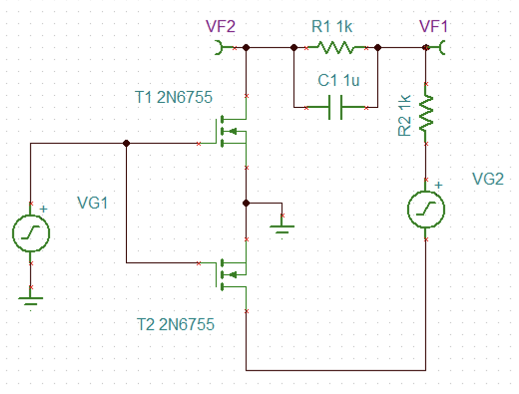
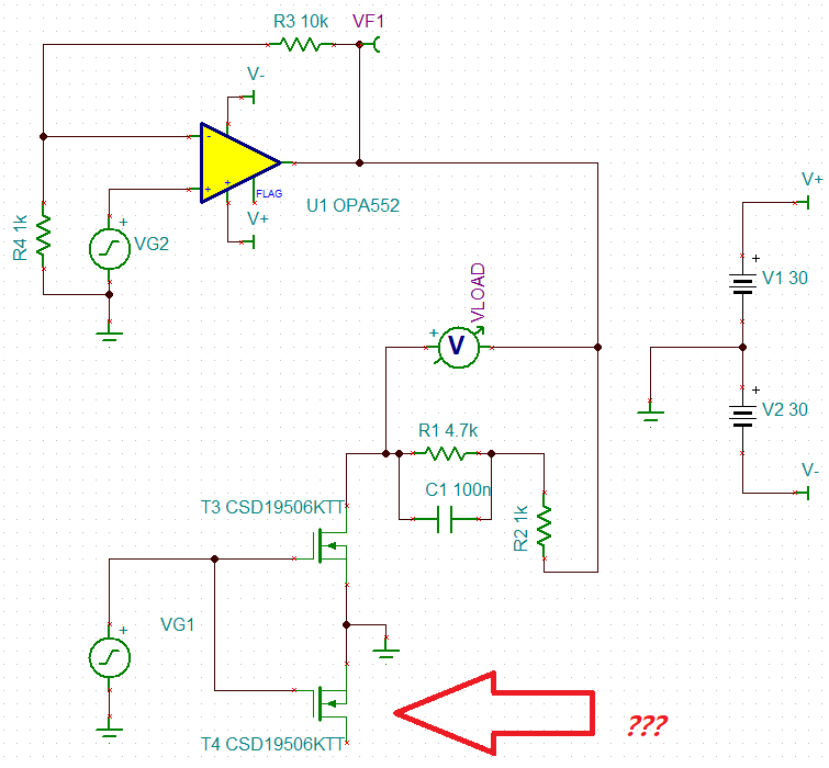
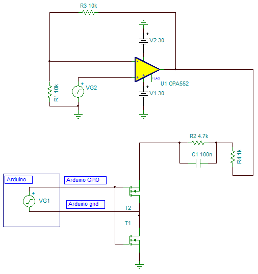
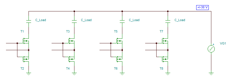
I was trying the TIDA-00377 Solid State Relay SSR using TI TINA 9. I have a custom capacitive load and a sine wave function generator (±30V, 2kHz).
My plan was using an Arduino Uno's 5V GPIO to toggle the NFET.
Since I couldn't find the CSD19506KTT from TINA, I chose a general NFET 2N6755 for the simulation.
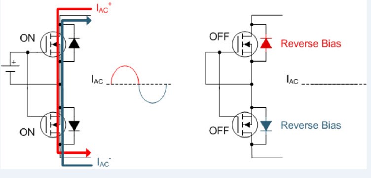
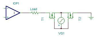
From this article,
I was expecting the AC signal to be flowing through the NFETs when the gate voltage is high.
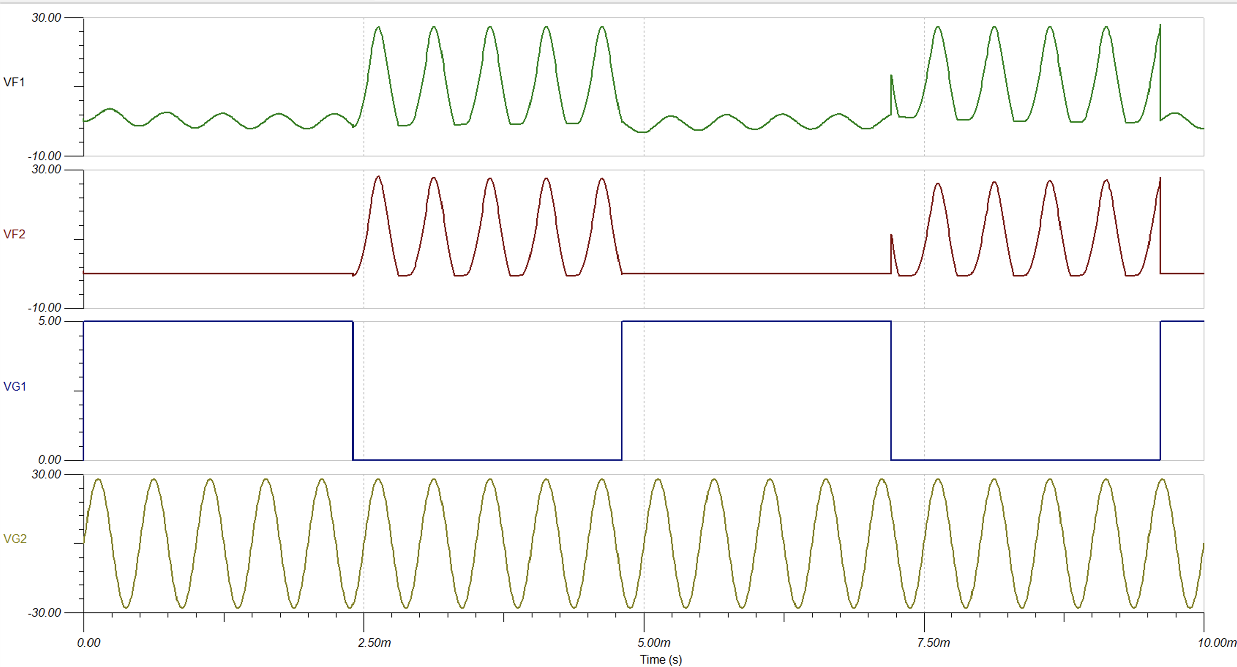
Whereas my simulation result seems like the function generator signal is connected when the gate voltage is 0V, the same GND level from the Arduino board. May I ask
Q0. Is my schematic correct? I thought I followed the TIDA-00377 correctly.
Q1. How can I import the CSD19506KTT into TINA 9? I want to simulate using my desired MOSFET if possible.
Q2. From the outputs (VF1 & VF2), I wanted the VF2 to be 0V when the SSR is off. However, negative voltages are shown.
How can I make this 0V? Should I add a pull-down resistor?
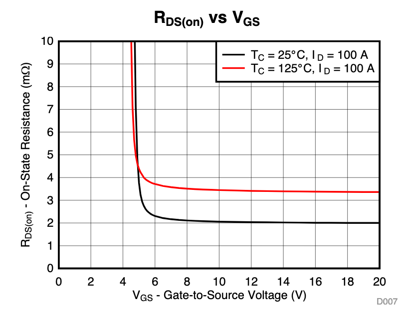
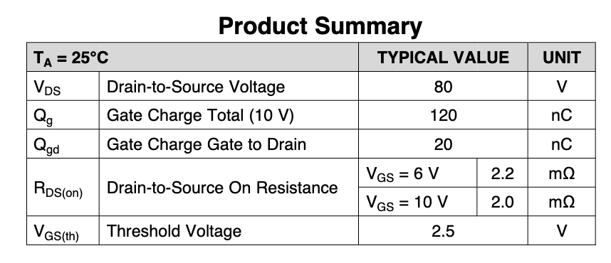
Q3. Using 5V to toggle the gate, can CSD19506KTT be used for the SSR application?
Q4. Compared to the schematic, I need to connect the function generator's negative terminal (-) to Arduino's GND.
Whereas the above schematic has separated the negative terminal from GND.
How should I change the schematic to connect both the negative terminal to GND?


