This thread has been locked.

If you have a related question, please click the "Ask a related question" button in the top right corner. The newly created question will be automatically linked to this question.

BQ76920: malfunctioning with several issues

Part Number: BQ76920

Hello,

I'm experimenting several issues on a design using bq76920(06) to monitor a 3S LiFePo4 battery pack. First oddity, the reading of ADCGAIN1/2 is not consistent across power cycles. Second, OVRD_ALERT is always set and it cannot be reset, while ADC_ENABLE reads always '0' although being set (and the ADC works anyway). Next, the cell voltage reading is very strange and seems "shifted" by one cell, that is, voltage of cell 1 is reported on cell 2 and so on, while the reported voltage for cell 1 is around one third of the nominal cell voltage. Here follows a sample readout (in mV after conversion): [1] 974, [2] 3270, [3] 3068, [4] 1, [5] 12, [6] 3064, [7..15] 1 (where "1" is ADC_OFFSET).

Some notes:
- ALERT pin has been physically diconnected from the controller and filtered with 470pF + 470K pull-down.
- A 2.2uF bypass capacitor has been added to REGOUT
- The same behaviour has been observed on three different boards
- Boards have been checked against soldering issues

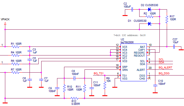
Here follows an extract of the schematics - the bq is attached to an MSP430 (powered by an alternate LDO) and drives an high side power switch for the discharge path (no charge path implemented).

Any suggestion and help to find the (giant?) culprit is highly welcome, we are currently stuck.
Best regards,

Stefano

  • Hi Stefano,

    The minimum recommended capacitance for CAP1 is 1 uF and is a typical component vs the 0.1uF shown. I don't know if that would cause the issues you are seeing.  REGOUT is used internally for the communication interface and must have a capacitor which you indicate has been installed.  REGSRC also must have a capacitor, 1 uF is the minimum recommended and a typical component value.  

    You might look at the I2C lines to confirm the edges are good, pull ups are not shown on the schematic clip but must be present or the bus would not work.  Also check the clock speed, the BQ76920 maximum clock frequency is 100kHz.  A recent user reported inconsistent gain values when using a faster clock.  

    You might check the ALERT pin with a scope to see if the clear command is effective.  The 470pF 470k pull down has about a 250 us time constant, a longer time constant on the pin can allow it to still be high when the pin checks it as an input and you might see it drive high again.  Also in debug be aware that if the CC is set to continuous the ALERT will be set each 250ms cycle. 

  • Gotcha!
    The I2C frequency was well above 100kHz, putting it back in range fixed all the issues.
    Thank you so much for your prompt and valuable reply - almost sure I was missing something really big... :-)