This thread has been locked.

If you have a related question, please click the "Ask a related question" button in the top right corner. The newly created question will be automatically linked to this question.

UC3843: UC3843 frequency changes after slope compensation

Part Number: UC3843

We all know that UC843 is a fixed frequency IC, RC pin determines the frequency.The maximum duty cycle of UC3843 is 0.95 from datasheet.But when I used slope compensation, the frequency changed.why?
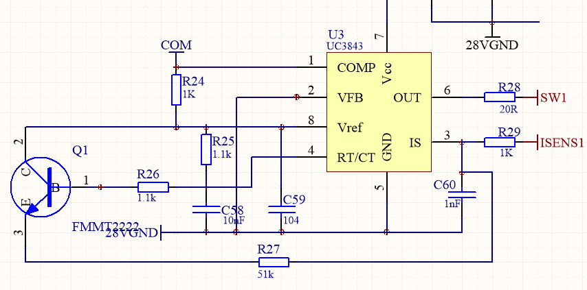
Both the experiment and the simulation saw the same conclusion.
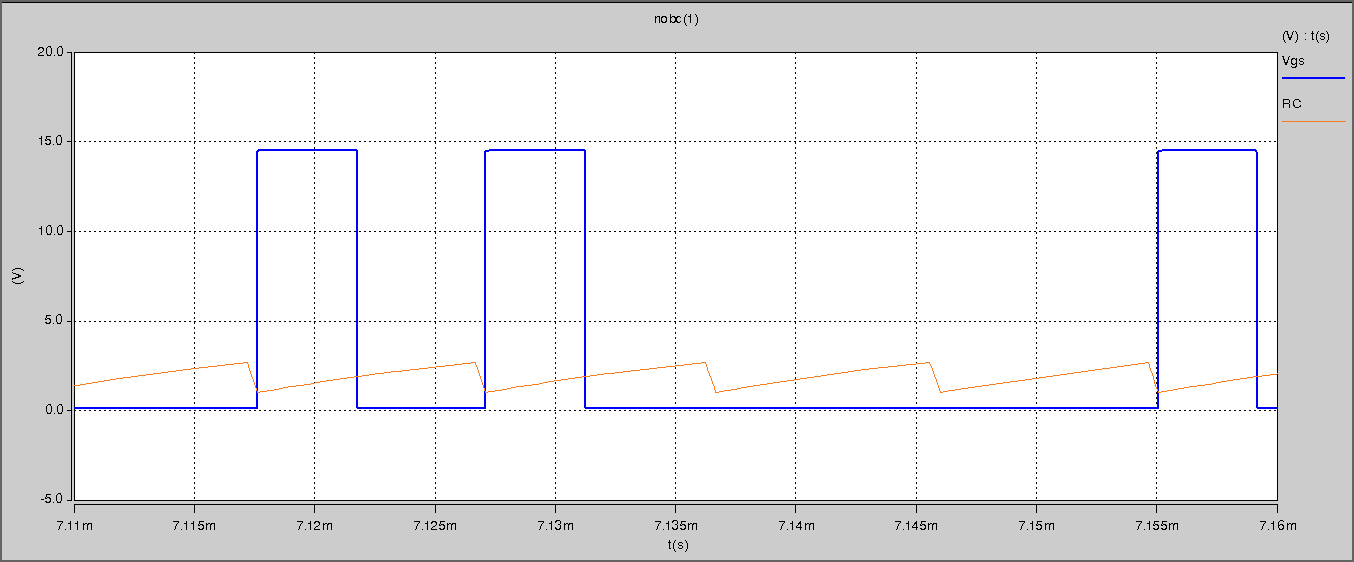
I guess the 4-pin(RC-pin) that affects the frequency decision circuit

  • Hello Shunheng,

    Your waveform actually shows  a fixed frequency oscillator. This is the RC waveform.

    The other waveform is labelled Vgs and this shows the the gate drive.

    The gate drive is missing pulses during two clock cycles and this is happening because the COMP pin voltage is zero during this time.
    If you want a fixed gate drive then the COMP voltage should be a fixed value.

    Regards

    John

  • John Griffin1 said:

    Hello Shunheng,

    Your waveform actually shows  a fixed frequency oscillator. This is the RC waveform.

    The other waveform is labelled Vgs and this shows the the gate drive.

    The gate drive is missing pulses during two clock cycles and this is happening because the COMP pin voltage is zero during this time.
    If you want a fixed gate drive then the COMP voltage should be a fixed value.

    Regards

    John

  • Hello John,

    The COMP pin voltage is zero during this time. I have checked it before, not for this reason.

    The COMP pin voltage is 2.2V during this time.

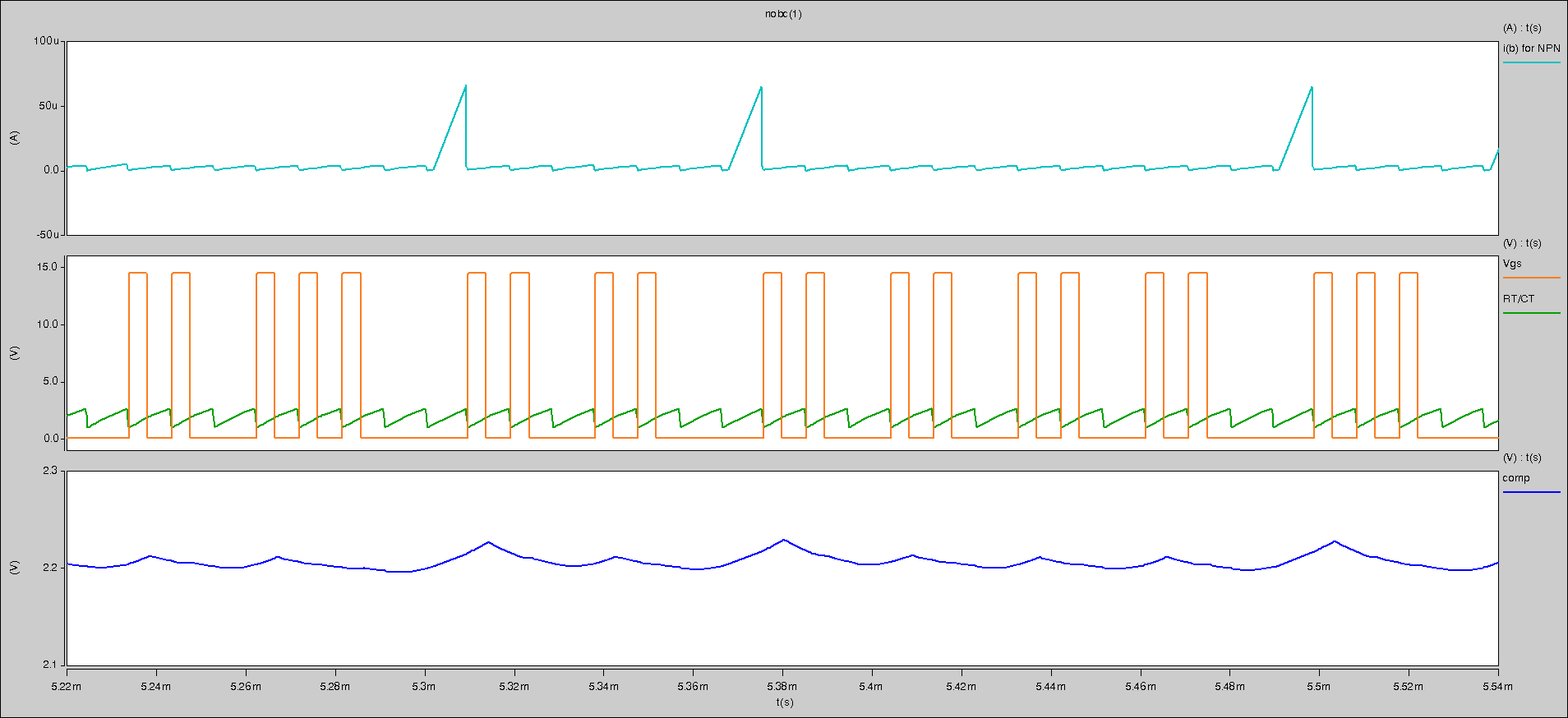
    The Figure 3 is comp waveform.

    The Figure1 is Q1(NPN) ib waveform.(You can take a look at the schematic of the first question.)

    I think that the current of the RT/CT pin is drawn, affecting the internal logic of the RT/CT pin?

  • Hello Shunheng,

    Please check the signal on IS and COMP.
    This is the input to the pwm comparator
    If COMP exceeds IS then you should  get an OUTPUT signal

    Also
    VFB is connected to GND and this will force COMP high.
    Why do you have a 1k resistor from Vref (5V) to COMP ?

    Regards

    John