This thread has been locked.

If you have a related question, please click the "Ask a related question" button in the top right corner. The newly created question will be automatically linked to this question.

TPS5450: Converter Efficiency vs Overall Efficiency

Part Number: TPS5450

Hi,

We are using TPS5450DDAR in our design to generate 5V output delivering 750mA. This is derived from a input voltage supply of 12.36 to 13V.

The practically calculated efficiency based on the measured input/output powers turn out to be ~88%. The efficiency curve provided in datasheet (12V to 5V conversion) shows around ~93% efficiency for the same 750mA of the output current. So, here we see difference of ~5% between the two & we are trying to understand this difference. We note that the inductor and diode part numbers we use are different from what is used in the EVM.

Does the efficiency curve given in the datasheet constitute for the TPS5450's power loss alone? Total power loss in TPS5450 calculated using the equations in the datasheet(shown in the attached image) for various load current is close to the conversion losses reverse calculated based on the XY values in the efficiency curve for the particular load current.

We are using the following two parts in our design in the power stage.
Inductor : HCMA0703-330-R
Diode : DB2431200L

We had tried changing the diode part to EVM's B540 and the inductor part to a lower DCR part IHLP4040DZER150M8A & Both the changes havent helped. However, We havent tried the same together but we dont think this should help us.

Also, Is it possible for you to the test the efficiency of the EVM design with 12V input to 5V output delivering 750mA?

Looking forward for your reply at the earliest.

Thanks

  • Hello ,

    What is the Switching frequency used in your application ? Is it the same switching frequency as mentioned in the datasheet or EVM ? 

    ---Ambreesh 

  • Hi Ambreesh,

    The TPS5450 we use is a fixed frequency regulator(500kHz nominal). Here is the link for the datasheet we follow.

    https://www.ti.com/lit/ds/symlink/tps5450.pdf

    Edit :

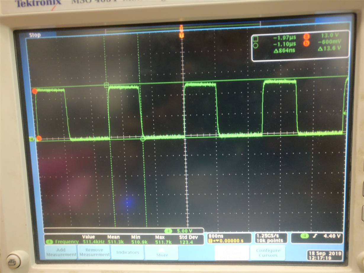
    On probing the PH pin of the regulator, We see ~512kHz with an ON time of 864ns when delivering the 750mA load.Please see the waveform attached.

    I would like to clarify one my earlier point(below) that we don't have an EVM for this at hand and we had few B540 parts at our stores so that we could replace and test the same. This is reason why I had requested for possibility to test the efficiency in the EVM setup available with you for TPS5450

    "We had tried changing the diode part to EVM's B540 and the inductor part to a lower DCR part IHLP4040DZER150M8A & Both the changes havent helped. However, We havent tried the same together but we dont think this should help us.

    Also, Is it possible for you to the test the efficiency of the EVM design with 12V input to 5V output delivering 750mA?"

    I hope this helps and looking forward for your reply.

    Thanks

  • You are getting about 88% efficiency with 33uH and DCR of 220mohm . THe EVM is using inductor that has DCR of 20mohm .

    The delta  DCR loss = 0.1125W(I^2Rdcr losses) 

    This is about 3% of total output power (3% of total 3.75W output power) .

    Use 33uH 20mohm inductor to achieve above 90% efficiency .

    Further What is the input cap used used ? Are there any input filter etc ?

    ---Ambreesh

  • Hi Ambreesh,

    As per your suggestion, We managed to fit in a lower DCR inductor (CDRH127/LDNP-220MC) in the place & we were able to observe improvement in the overall efficiency. However, I am not sure why we couldn't observe the same when we changed to IHLP4040DZER150M8A  part which has relatively lower DCR compared to one we use in the board. We will be re-checking on the same.

    For the Input and Output Caps, We use the following configuration.

    Input Cap : 1x 10uF + 1x 0.1uF (Both Ceramic)

    Output Cap : 1x 100uF (Electrolytic) + 2x 47uF + 1x 1uF (Both Ceramic)

    Thanks,