This thread has been locked.

If you have a related question, please click the "Ask a related question" button in the top right corner. The newly created question will be automatically linked to this question.

UC3525A: output A & B of UC3525A

Part Number: UC3525A

Hi TI team

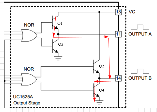
I'd like to know output A & B of UC3525A.

Are they reverse each other, or phase difference angle??

I want to combine the two output to achieve a 99% duty cycle.

Could it be possible?

Thanks

  • Hi Chun Hung Chen,

    Output A and output B are complementary, but with a dead time.  From the figure 2 in the datasheet, the dead time can not be eliminated no matter what value the capacitor on CT Pin and dead time resister between CT pin and discharge pin   are.

    Thus they can't be combined together to achieve a 99% duty cycle.

    Regards,

    Teng

  • Hi Teng

    Thanks

    I don't get the chart above. Does the charging time need 1us-10us?

    If so, how can it work in 500kHz?

    Can I combine the two output together?

    How many duty can I get?

    Thanks

  • Hi Chun Hung Chen,

    You can find this figure in page 7 of the datasheet, which is located here.

    http://www.ti.com/lit/ds/symlink/uc3525a.pdf 

    When switching frequency is 500 kHz (period is 2us), a dead time larger than 1 us will force to no PWM output. 

    The two output pin can't be shorted together.  As shown in the figure, when output A  is high and output B is low, the Q4 is turned on, which will pull down the output A to low voltage, and vice versa. Thus you can not get any output. It even will damage the IC.

    Regards,

    Teng

  • Hi Teng

    Thanks

    When switching frequency is 500 kHz (the period is 2us), a dead time larger than 1 us will force to no PWM output. 

    It doesn't make sense, the duty of each output(A & B) is 49%. And, dead time larger than 1 us.
    It's only 25% duty to put PWM.

    The two output pin can't be shorted together.
    I think it needs some circuit to combine them.
    Maybe the "or" IC or an adding circuit.

    Thanks

  • Hi Chun Hung Chen,

    In a switching period, there are two dead time. The PWM will be disabled if the sum of them ia larger than the switching period.

    Regards,

    Teng