This thread has been locked.

If you have a related question, please click the "Ask a related question" button in the top right corner. The newly created question will be automatically linked to this question.

LM5060-Q1: Facing issue in using LM5060 for inrush current limiting/ DC link capacitor precharge

Part Number: LM5060-Q1
Other Parts Discussed in Thread: LM5060, CSD19536, LM76202-Q1, LM5069,

Hi All,

I am using evaluation board in  LM5060 for 48V application. I am trying to control inrush current for DC link capacitor charging by adding capacitor on gate of mosfet.

My requirement is to complete capacitor pre-charge in <100mS

and precharge current should not be greater than 200mA..

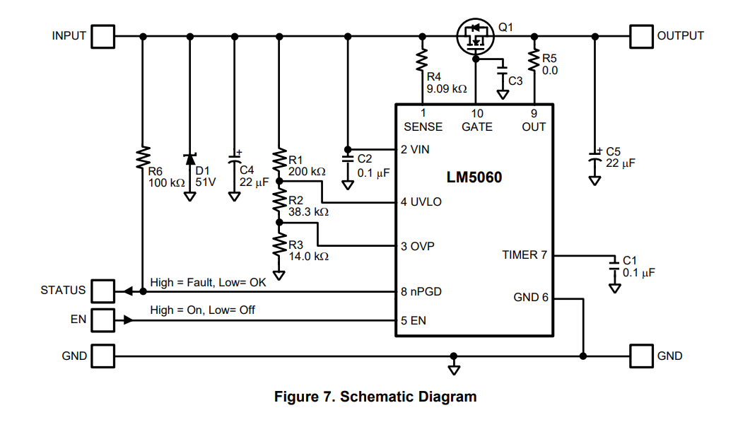
please refer attached schematic of LM5060 evaluation board which I am using. 

Input voltage=44V

C3=60nF

Q1=CSD19536

R1=49.9K

R2=2.7K

R3=2K

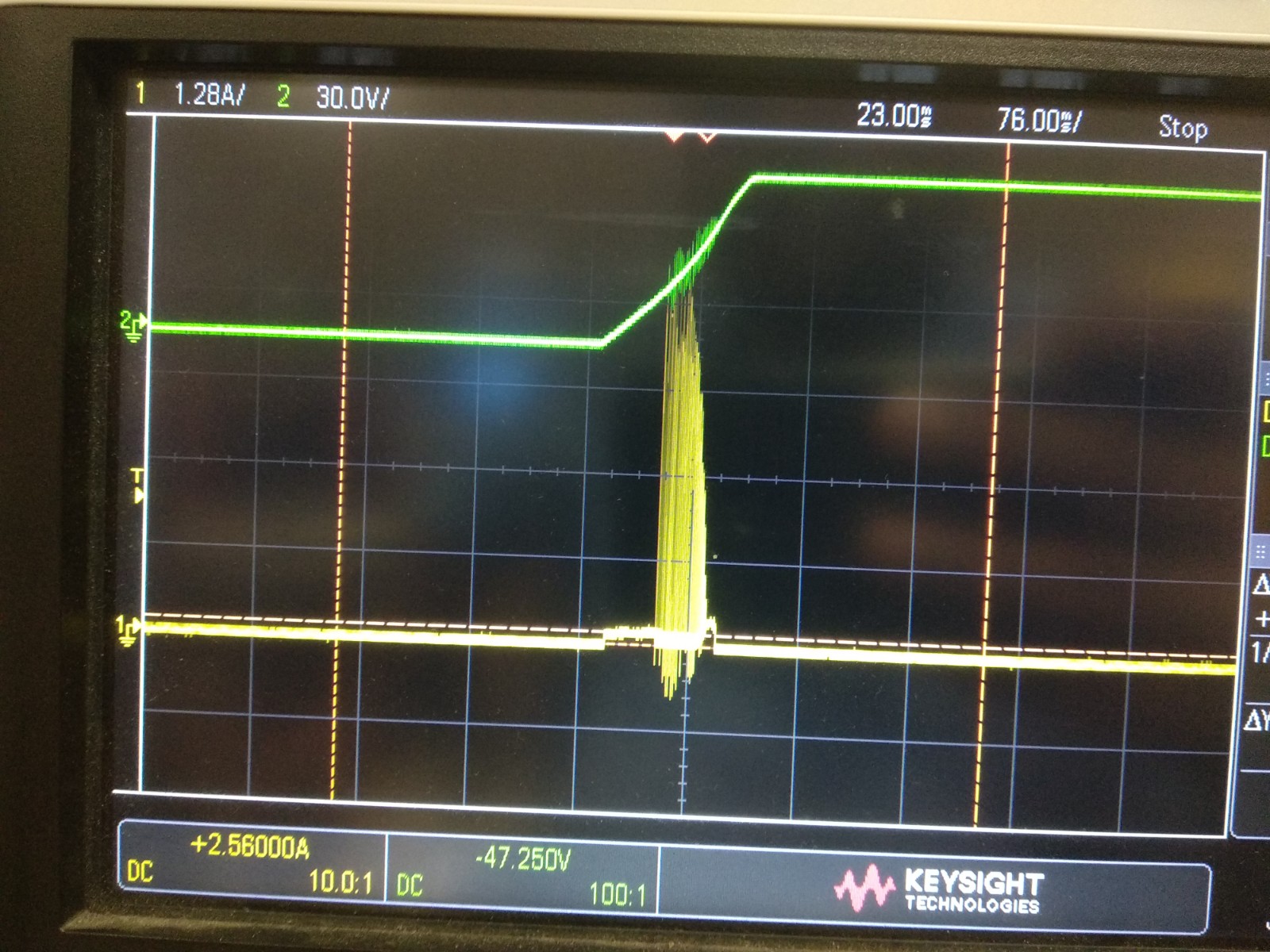
When I am giving 44V to input and enabling LM5060 by giving enable signal.. my output is rising linearly in required time.

Ideally it should take nearly constant current during capacitor charging, but it is taking high current pulses.which is not expected.

Please refer attached wave forms for output voltage rise and input current.(yellow=output voltage, Green= input current)

Regards,

Pradip

  • Hi Pradip,

    Welcome to E2E! 

    MOSFETs having higher transconductance ‘gfs’ leads to faster turn-on and higher inrush currents. This results in inductive kick-back effect in source follower configuration during start-up interval and shows hiccup behavior. We can overcome this scenario by adding more capacitance b/n GATE to Source for the external FET. Higher capacitance value helps to reduce the inrush currents as well.

    Can you leave C3 OPEN and add 22nF b/n GATE to Source of external FET and check.

    I recommend to use LM76202-Q1 where inrush current can be programmed easily through an external dvdt capacitor.

    BR, Rakesh

  • Hi Rakesh,

    As per your suggestion I kept C3 open and added 22nF between gate and source of MOSFET; but it is not solving my problem.

    Current spike increased in this. Please refer attached waveform for same.

    Recommend part by you is not suitable for my application, as my continuous current is 10A through switch.

    I have added 10E gate resistance in series with mosfet gate, it solved issue of current spikes; Refer schematic for it.

    But my requirement for charging current is 200mA(max peak charging current should not be greater than 200mA & precharge should be completed in 100mS); You can see waveform it is taking peak current nearly 370mA. I am not finding any way to meet required specifications.

    Kindly Support.

    Regards,

    Pradip Magar


  • Hi Pradip,

    As the capacitance of the external MOSFET varies with the Vds voltage, we can expect some non-linearity. Do you need Q1 device for your application ? Else LM5069 would be good option. The external dvdt circuit shown in the front page of the LM5069 datasheet would dominate to make a linear soft-start circuit. 

    with LM5060-Q1, try with resistor 2.2k Ohm in series with C3.

    BR, Rakesh

  • Hi Rakesh,

    I tried with 2.2K added in series with C3 but no major change. It added some delay in initial ramp up but current is not controlled as required.

    I need Q1 part as it is automotive application.

    Thanks & Regards,

    Pradip Magar.

  • Hi Pradip,

    LM5060-Q1 is designed for protection against soft overloads and overvoltage protection. The drive is not linear (to maintain constant inrush currents) when you try to do inrush control at such low levels.

    What is the risk if inrush current is 370mA (as per above test waveform) ? 

    BR, Rakesh

  • Hi Pradip,

    What is the risk if inrush current is 370mA (as per above test waveform) ? 

    BR, Rakesh

  • Hi Rakesh,

    As it is clients requirement, we are working on it.

    Requirement is we should complete pre-charging in <=100mS and max peak current should not be greater than 200mA.

    Thanks & Regards,

    Pradip.

  • Hi Pradip,

    Understood. Thanks!

    May be you have to look for alternate solution to achieve constant 200mA.

    BR, Rakesh