This thread has been locked.

If you have a related question, please click the "Ask a related question" button in the top right corner. The newly created question will be automatically linked to this question.

BQ34Z100-G1: Higher capacity(>29Ah) & higher current(>29A)

Part Number: BQ34Z100-G1
Other Parts Discussed in Thread: BQ76920, BQ78350, BQ78350-R1

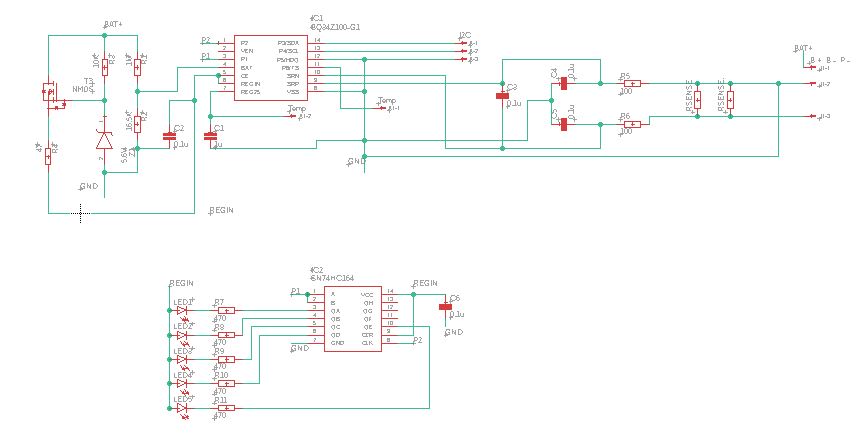
I want to use BQ34Z100-G1 in one of my projects for battery gauging purpose but the battery capacity is >30Ah & current is >100Amps.

Battery Pack is 13s13p NMC(18650) cells of 2600mAh.

Battery Voltage is 54.6 Volts. Capacity is 33.8Ah. Max Discharge current 130Amps. Charging current 20Amps.

How to select the resistors for voltage divider circuit? In SLUA760 calculation is given with respect to voltage only.

How to design the translation circuit for higher current & capacity?

What should be the values & ratings of resistors, NMOS?

As it should not damage the IC and gauge will work properly. 

  • HI Samruddhi,

    We don't recommend using the gauge for such high currents, you will have scaling issues if you are not experienced with using this and your design will have issues. Please look up the bq78350 or the bq76920, those are better options for you  and are more stable for higher voltages and currents.

  • Dear Sir,

    PFA

    Thank you for your feedback.

    But I have designed the PCB as per scaling calculations.

    I'm using the 1Mohm series resistor.

    Please check my attached board layout & schematic for the same.

    Regards,

    Samruddhi

  • Hi Samruddhi,

    Please don't attach jpegs as I can't read them this way. Please export to pdf so that I can review them here.

  • Dear Sir,

    PFA pdf file of sch & brd.

    Please zoom into it so that you can view it properly.

    In the brd file, I have removed the common ground plane for capturing purpose.

    It's a 2 layer PCB.

    B - (Battery Negative) is connected to ground. 

    Regards,

    Samruddhi

    BQ34Z100-G1_sch.pdf

    BQ34Z100-G1_brd.pdf

  • Hi Samruddhi,

    Your design basically follows the schematic so it's OK. You can adjust the voltage divider so that the ratio of the voltage seen by the gauge is 1V or less. To allow some margin, we advise that the divide ratio to the gauge be less than 900mV. The gauge by itself doesn't consume much power, so you don't need high power resistors, the standard ones (1/10W chip resistors with 1% or 5% tolerance). The MOSFETs can be up to 60V and should handle at least 200mA. Again my advice is at those high currents you are better off using a monitor like the bq78350-R1 instead of the gauge.

  • Dear Sir,

    Thank you so much for your guidance.

    I have considered using 78350-R1 but making its schematic & board is a long process.

    Also after watching TI's training video on Battery Gauging I thought Impedance Track will be easy to implement rather than CEDV.

    Please guide me on the same whether to go for Impedance Track or CEDV algorithm.

    Regards,

    Samruddhi

  • Hi Samruddhi,

    It's up to you what algorithm you want to use. CEDV is actually simpler than IT. That and the fact that the bq78350-R1 is a more proven solution is why it might be better to use that.