This thread has been locked.

If you have a related question, please click the "Ask a related question" button in the top right corner. The newly created question will be automatically linked to this question.

TPS23861: tps23861 configuration

Part Number: TPS23861
Other Parts Discussed in Thread: TPS23754,

HI

Currently my client is developing ip cam using tps23861 and tps23754.

There were three customer inquiries

We would like to apply tps23861-tps23754 x 2(parallel).

One TPS23754 is continuously connected.

The connection of the second TPS23754 is then different.


1) Is TPS23861 automatically negotiated and changed in the above situation? (POE +-> POE, POE-> POE +)

2) How do you monitor PSE from the PD side?

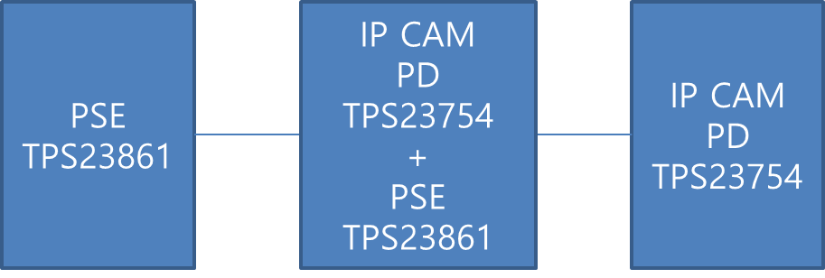
3) In order to connect 2 IP CAMs, we want to configure as below due to length problem. Is it possible?

  • Hi Kim,

    What is the power level of TPS23754 on the middle block? Also what is the power level of the TPS23754 of the last block? Is this system a closed system (meaning you have control of all blocks and end user will be only be able to use equipment that are in this system and nothing else)? Also, are you trying to be compliant to the IEEE standard? Or is your solution custom?

    At a high level, if your TPS23754 load is 13W then it will be possible just to do this in hardware. TPS23861 will be set to automode on both blocks and the TPS23754 can be set to 13W on both blocks.

    Please let me know if this is clear. Thanks!

  • Hi

    At present, the customer wants to develop the first stage. The last camera is determined by the end customer (may not be used).
    The cameras all attempt to use products that comply with IEEE802.3af. (13w class)
    Just when using the second camera in that situation,
    The distance is so long that it cannot be powered through the front PSE.
    As a result, I would like to develop PD on the first camera and add power to the second camera by adding PSE IC.
    We know that there is no connection from PSE to PSE. Is it possible to use PSE-> (PD-> PSE-)> PD as above?

    For example, the second camera is said to be disconnected.
    If the second camera is connected in this state, can the PSE IC automatically recognize this and change from AF to AT automatically?

  • Hi Andy,

    In short, in order to make the TPS23861 switch between AF and AT, you need a microcontroller to let the TPS23861 output AF, AT power at the PSE output.

    However, if you know that the third block will always be AF then this might not be necessary. For example, if the middle block TPS23754 always asks for Type 2 power and the TPS23861 first block always outputs AT power, then as long as the TPS23754 DCDC output power is 10W, you will always have 15W available to the TPS23861. Since you know the third block will always be 13W, then the TPS23861 middle block (in automode) will automatically send 15W to the requested 13W from the third block.

    A lot of end equipments do this in pass through systems. They will have marking on the PSE output that says "Type 1 PSE port" or "IEEE802.3.af PSE port". Then end user knows to only connect Type 1 PD.

    I recommend ordering a TPS23861 EVM and TPS23754 EVM to evaluate its performance in your system.

    http://www.ti.com/tool/TPS23861EVM-612

    http://www.ti.com/tool/TPS23754EVM-383

    In addition, when you make your PSE design for middle block you can copy the single port PSE design below:

    http://www.ti.com/tool/TIDA-00465

    Thanks!