This thread has been locked.

If you have a related question, please click the "Ask a related question" button in the top right corner. The newly created question will be automatically linked to this question.

TPS54160A: inductor whistle

Part Number: TPS54160A

Hi,

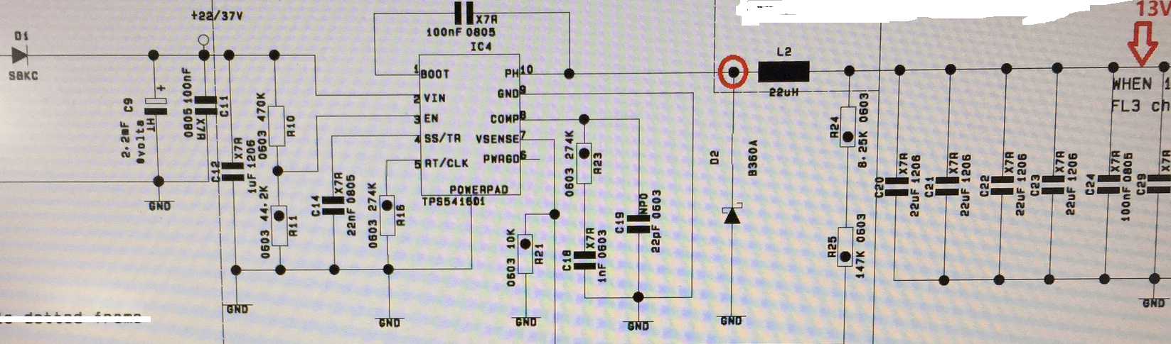
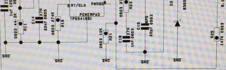
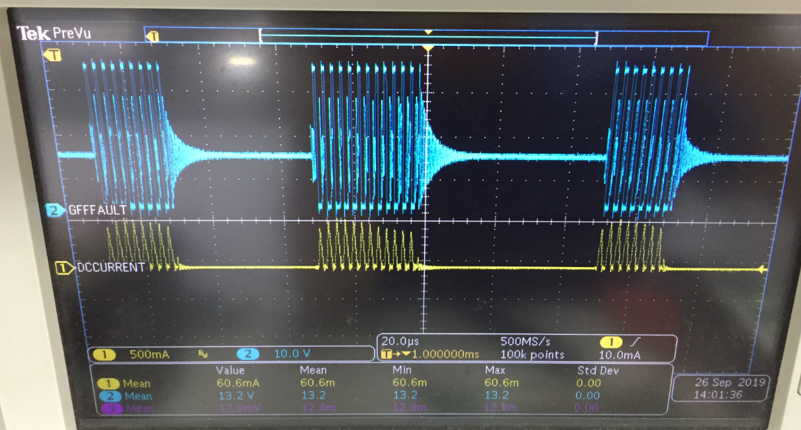
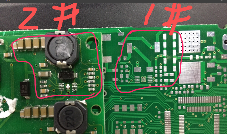
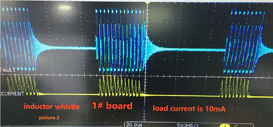
I used TPS54160A for 24VDC to 13VDC buck circuit(2# board). as the picture1 shows.load current is very small,about 1--10mA

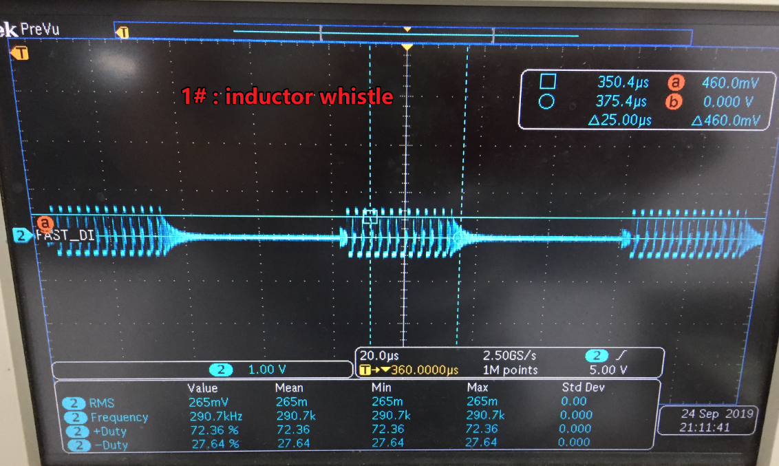
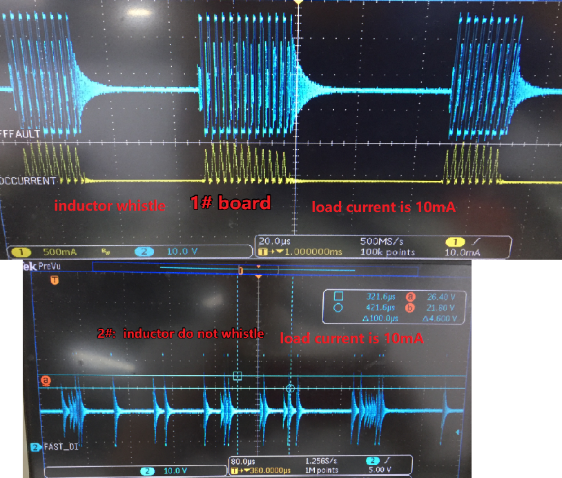
Now inductor is very whistle,but i do not know why inductor whistle and how to solve issue

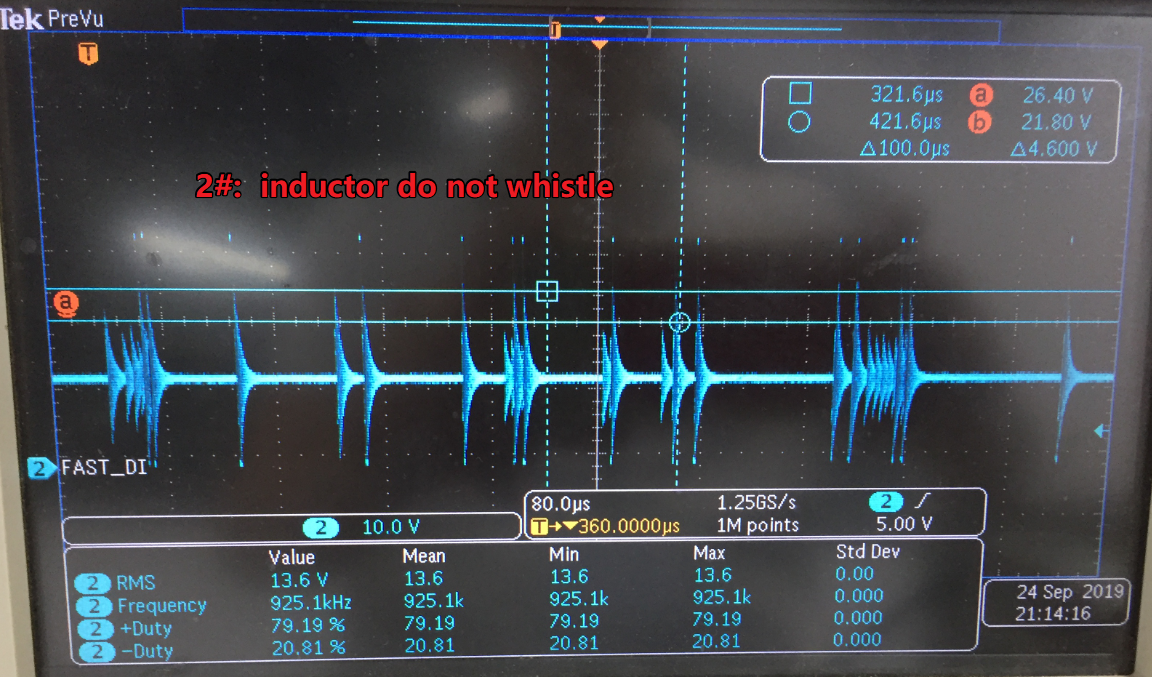
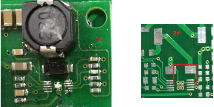
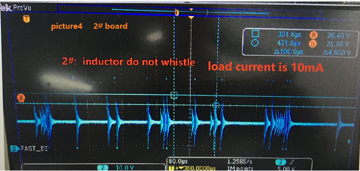
We used TPS54160A to do the same buck circuit(24VDC to 13VDC), see picture4(1# board)but  inductor is not whistle,it is very good,

I really want to know why inductor whistle on 2# board,and inductor is not whistle on 1# board?

What I don’t understand is that buck circuit on 2# board is as the same as buck circuit on 1# board,and all components are the same

I only found two different points.

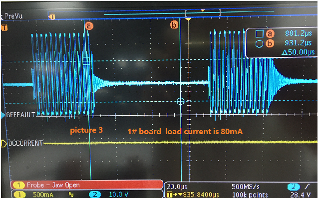
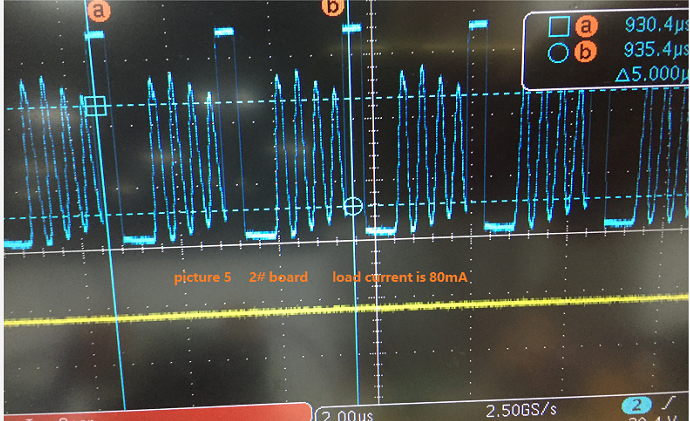
one point:regarding to the test waveform on red circle,the difference between 1# board and 2# board is very big. I believe that you can find the answer from this point.

other point:pcb layout have a little different,trace width in red box of 2# board  is too small.

Thanks a lot!


  • sorry,

    picture1 is not Incomplete,so add the picture below.

    In addition,output voltage on 2# board is 13V,

    when  the output load on 2# board is changed,  inductor still whistle

    Thanks!


  • Hi Jack,

    It seems your compensation components has wrong values and smaller inductor is used in the schematic. I would strongly recommend to make sure your BOM compnoents matches with design requirements before sebugging. Please follow this link to get your BOM values right.

    Best Regards,

    Ankit Gupta

    Application Engineer.

  • due to inductor of 1# board is not whistle, is very good,  buck circuit on 2# board is as the same as buck circuit on 1# board,and all components are the same

    please do not doubt schematic of 2# board,

  • Are you claiming to have part to part varaince in performance due to inductor accoustics?

    My thinking is proper magnetic selection while help reduce the accoustic noise.

    What is your part number of the inductor?

    Additionally, I can not tell by your time scale, but the switching frequency may be different between the two waveforms, but neverthless, frequencies may be present in the audible range. 

    You could also look into a converter who operates at a constant frequency to mitigate the issue of switching componets in audible range?

  • Hi,

    sorry!waveform on 1# board is not correct,correct waveform as blow:

    Now I found the reason for inductor whistlering:1# board waveform does not seem to be normal,and TPS54160A seem to be restart

    i do not know why???   beause Schematic and components are the same as 2# board

    Compared test waveform as blow:

    Thanks a lot!

  • working frequency is 400Khz

  • Hi Jack,

    Glad the problem is resolved. 

    Best Regards,

    Ankit Gupta

  • Hi,

    My probem is not solved,now I have  a  summary:

    1,I want to clarify:whistle is not inductor,actually is five output ceramic capacitors

    2.differece between 1# board and 2# board  is pcb layout (Schematic and all the components are the same),

    3. pcb layout  differentce:I  check that the power ground of the buck and the signal ground of the chip is not separate,maybe there are other differences,but i don't  have found now(see below picture 1)

    4. differentent pcb layout  causes the voltage waveform at the connection of the inductor and the diode to be completely different.

         1# board:

         when  load is light(about 10mA), the frequency is not fixed , it is not  jump mode.      (see below picture 2) 

         when  load is not light(about 80mA), the frequency is  not fixed , because  keep on hic cup,it is big waveform and small waveform,so PS54160A  seems to be no continuous working. (see below picture 3) 

         2# board:

         when  load is light(about 10mA), the frequency is not fixed because it is a jump mode.     (see below picture 4)

         when  load is not light(about 80mA), the frequency is  fixed ,about 400kHz  (see below picture 5)

    So,i want to know that waveform(1# board ) of the load 10mA and 80mA are normal or not 

       1.if it is normal, only problem is whistle

       2.if  it is not normal,how to do deal it ?  

            step1:Relayout,but this problem  can't be solved ,because the board space is limited

            step2:if step1 do not solve,use step2

                  charge some component parameter values,i do not know which components are changed and  how much to change?

            step3:if step2 do not solve ,add use step3 

                        Increase or decrease the inductor value


            Thanks a lot!

  • Hi Jack,

    I would highly recommend to get the compensation components value right for your application, there is a high probability that part is slighly unstable and board parasitics making it worse. Please follow this link to get all your components value right : link.

    After making your changes please share your updated schematic and layout for review.

    If your application allows you, we recommend using the parts having Forced PWM option i.e. fixed frequency across loads. This should elimate your whistle issue.

    Best Regards,

    Ankit Gupta

    Application Engineer