This thread has been locked.

If you have a related question, please click the "Ask a related question" button in the top right corner. The newly created question will be automatically linked to this question.

UCC5350: How to reduce gate ringing on IGBT gates using ferrite beads

Part Number: UCC5350

Hi,

We are running a Half-Bridge configuration of IGBTs (stgy40nc60vd) using the UCC5350 at 23Khz to drive an inductive load :

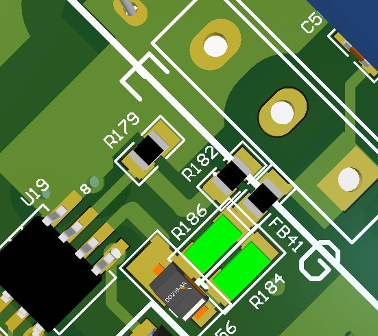
The schematic of the output from the UCC5350 is shown below for the High Side IGBT : 

We also have a 4.7nF capacitor across VCE which is not shown on the sch.

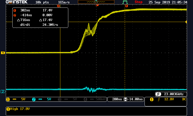
we saw quite a lot of ringing on the High Side IGBT and wanted to reduce this. We measured the ringing to be around 33Mhz and tried using a Ferrite bead in series with the gate (Wruth 742792097) but the results are the same and in fact may have gotten worse , The shots are below :

W/O Ferrite Beads :

With Ferrrite Bead in series with gate drive :

Can you please help me out.

Thank you so much

Tony .

  • Hi Tony, 

    Thanks for reaching out.

    Ringing at the gate can likely be traced back to the layout specifically trace inductance between the driver's output stage to FETs. The PCB trace connections should as short and wide as possible in addition to placing the decoupling capacitors directly across the VDD/VCC pin of the driver.

    Please share your layout snippet to rule this out or confirm it.

    Additionally, It looks like you're driving the IGBT at 13V (correct me if I am wrong!!), do you still see the ringing using VDD=18V? Why are you operating at 13V and not higher VDD=18V as shown on schematic?

    Regards,

    -Mamadou

  • Hi Mamdou,

    I have optimized the layout for the lowest inductance on the gate tracks. 

    I have made a change to the power input to the IGBTs and now we are running at 18V on the gate but the ringing still exists. 

  • Hi Tony,

    Could you please share a screen capture of your layout? Additionally, for the best results the ferrite bead should be very close to the IGBT gate. The good thing is that the ringing significantly reduced so far.

    Regards,

    Audrey

  • Hi Audrey,

    Here it is :

    High Side IGBT drive :

  • Hello Tony,

    The layout of the driver looks close to the IGBT with short traces. It seems the ringing is improved from the previous scope captures so it seems the bead is helping.

    To possibly reduce the gate voltage disturbance further, the turn on gate resistance can be increased which will dampen the ringing. Also you may want to review the ferrite bead to determine the impedance at the ringing frequency. An alternate bead with higher impedance at the ring frequency should reduce the ringing further.

    Audrey is the expert on this device so you should keep the conversation going with her.

    Regards,