This thread has been locked.

If you have a related question, please click the "Ask a related question" button in the top right corner. The newly created question will be automatically linked to this question.

BQ25713: BQ25713 waveform issue

Part Number: BQ25713

Hello

     Customer find out VBUS can not charge due to VSYS trigger Vth1 and retry 7 times still not achieve target voltage. So the charger is VAP failed. Per waveform, customer decrease OTG current to 0.3A and let VBUS charge to 20V. Then customer set OTG current 0.5A, but VBUS voltage will not start up after load current. 

1. why can support OTG current to 0.5A to happen VBUS not start up issue?

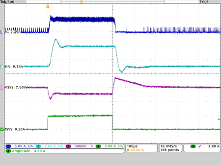
2. Below waveform, why VSYS has lager Vdop(300mV)?

3. What is OTG setting current ? Is VBUS charging current? 

4. After trigger Vth1 10us, VBUS just charge. Does it correct and have de-glitch time spec. ? (Datasheet specified 5us)

5. After  trigger Vth2, prochot# active after 6us, Does it correct and have de-glitch time spec. ? 

6. For 2S battery design, what is safe VAP setting that have not start up issue ? 

7. How to modify charger compensation to get better ripple/transient? 

8. Has Ripple/transient spec or waveform for 2S batter application for customer reference? 

BR

Patrick


  • Hi Patrick:
        

         This waveform is intel requested VAP mode opearation waveform. From your description I  assume customer want to work under OTG instead of VAP right?

          In VAP mode we are not expecting to add any load on VBUS. But OTG can support load at VBUS. To answer your question:

          1)  I suspect this is caused by VAP mode and OTG mode mixed up, please make sure REG35[5]=1 configure it work under OTG mode.

          2)  The drop is caused by inrush current coming out of battery when enable charging VBUS cap.

          3)  OTG setting current is the VBUS load current limit under OTG mode.

          4)  After system drop below Vth1, the VBUS cap begin to discharge. The de-glitch time in data sheet is valid.

          5)  That is correct.

          6)  You need configure part into OTG mode instead of VAP mode.

          7) We don't recommend to change our compensation network. 

          8) Below is the typical transient waveform under 2S application. Vin=12V, ISYS=0.2A~5A,VBAT=7.6V


  • Hello

                     Please refer to below. Thank you. 

          1)  I suspect this is caused by VAP mode and OTG mode mixed up, please make sure REG35[5]=1 configure it work under OTG mode.

    -->Customer would like to know behavior of VAP mode not OTG mode. Do we have behavior of VAP mode?

          6)  You need configure part into OTG mode instead of VAP mode.

    --> Customer need to know configuration of VAP mode not OTG mode. How to configure it on VAP mode? 

         7) We don't recommend to change our compensation network. 

    --> If have ripple and transient tolerance on customer side, how to improve it? 

    BR

    Patrick

  • Hello

                 Has any update for above question? Thank you. 

    BR

    Patrick


  • Hey Patrick,

    You can understand the feature of VAP mode in section 9.3.2 Vmin Active Protection (VAP) when Battery only Mode of the D/S. It is meant to support the system for the 1-2S battery configuration case in the event the system load has a very high peak. In battery only mode, the input voltage capacitors will be charged to the VOTG voltage and the converter will momentarily discharge to support the peak system load.

    As for ripple, consider a larger inductor or a higher switching frequency setting. For transient, consider adding a POS tantalum polymer capacitor to the output rail (SYS).

    Regards,

    Joel H