Other Parts Discussed in Thread: CSD17304Q3,
Comparing two part datasheets (CSD17575Q3 and CSD17304Q3) with identical packages (SON 3.3mmx3.3mm), looking at recommended footprints:
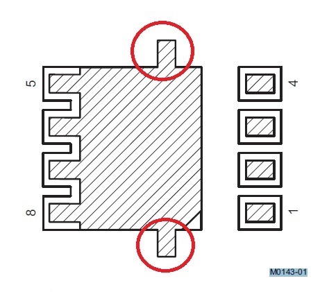
1) Recommended Footprint Drawing note M0143-01 for CSD17304Q3 shows a standard QFN footprint -- along with what looks like a stencil / solderpaste drawing showing with two side "wings" coming from the main pad in the center of the package (is this to deposit paste over the soldermask of the first drawing?)
2) CSD17575Q3 shows a more standard QFN package with a "recommended stencil drawing" that does not show these side "wings"
What is the recommended footprint for this "Q3" package? Is there a reason that these two tabs are not included in all "recommended footprint" drawings for this package?
Thanks - James


