


Hello,
I am designing a test jig for a PCB that we need to make a PCB production test for and I want to be able to quickly test the battery charger without using a physical battery in place.
The test need to verify the following:
- Toggle of the /CHG pin
- Verify charge current (~200mA)
- Charge complete
- Over temp battery charge stop
I am considering the follow circuit:
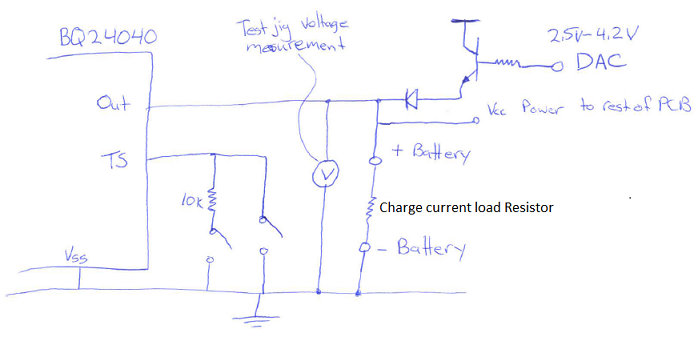
The 'Charge current load resistor' would be set to something like 18-20 ohm so that set charge current of 200mA could be achieved.
- So the test would start with the TS pin set to 10kOhm, DAC producing around 3.0V ( at the battery terminal) to produce a low battery condition
- Then the proper (PG) power would applied to Vin, it is expected that the BQ24040 input power would be applied and 200mA should output from the charger raise the voltage 3.8V to 4.0V
- Once observed the DAC would ramp to 4.2V-4.3V, to trigger a charge complete condition.
- The test would be repeated expect once charging current was reached the TS pin would switched from 10k to Vss (gnd), to produce battery over temp condition.
How likely is this to work as expected? Have I missed and consideration that would preclude this operation as I intended? If so, any suggestion on how I could resolve the issue be great appreciated.
Thank you very much,
Scott
