This thread has been locked.

If you have a related question, please click the "Ask a related question" button in the top right corner. The newly created question will be automatically linked to this question.

BQ27200DRKR backup when battery cuts-off

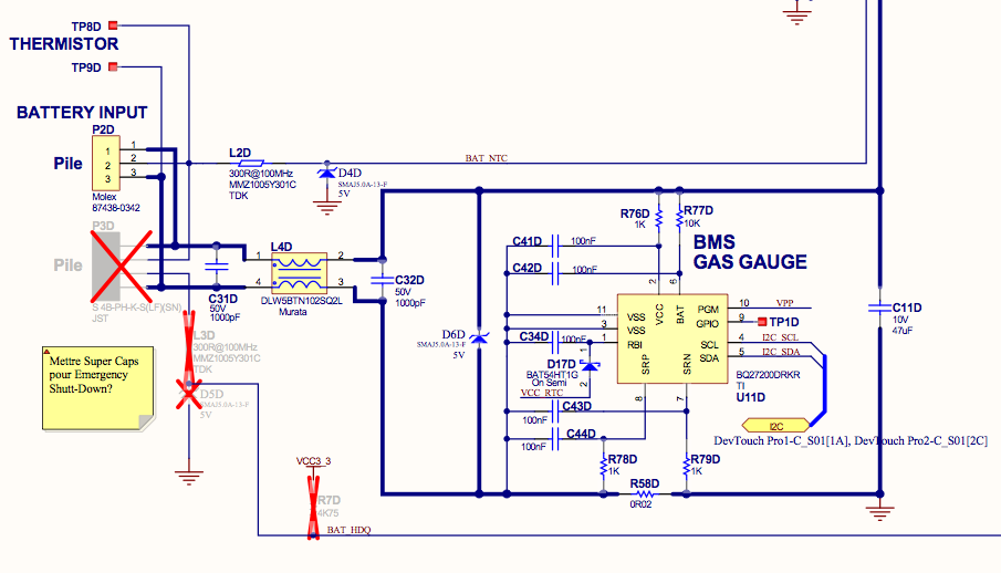
I am using the BQ27200DRKR (SINGLE CELL Li-Ion AND Li-Pol BATTERY GAS GAUGE IC FOR PORTABLE APPLICATIONS) in my design. For technical reasons, we could not put this device into our main Li-Pol battery cell. When the main battery is too low, it cuts-off thus removing power to this device which then loses its Coulomb counter value. When we recharge the main battery, the device is powered again but it has lost the main battery remaining capacity ! Is there a way I could use the 3V backup battery I have in this design to allow us to maintain the Coulomb counter value when the main battery cuts-off ?

Thanks in advance.

Pierre Richard

  • Pierre,

    The first option is to switch the part's VCC from the system voltage to your battery backup 3V source.  This way, the part never loses power.

    If this isn't an option, you may try something else:

    When the cell voltage goes too low, the 27200 uses capacitance hooked up to the RBI pin as a RAM backup.  In this mode, the gauge draws on the order of nanoamps.  What you can do is hold this RBI voltage up with your battery backup, and the gauge will hold the RAM information.

    There are a few notes about doing this:

    Due to ESD protection structures, RBI can only go 0.3V above Vcc while the part is on.  Therefore, if you connect your battery backup directly, you need to make sure that the backup voltage is less than Vcc + 0.3V.  This is spec'ed in the data sheet. 

    If this isn't possible, note that the capacitance on the RBI pin will hold the RAM data for a minute or two before the leakage pulls all of the charge off of the capacitor.  Because of this retention, you could also do a break-before-make connection of the battery backup to the RBI pin that is triggered by loss of battery voltage. 

    Let me know if this helps,

    Charles

  • Hi

    Please find my answers in red lower in the text.

    Pierre Richard
    Primma Microtechnologies


    Pierre,

    The first option is to switch the part's VCC from the system voltage to your battery backup 3V source.  This way, the part never loses power.
    Could the BQ27200DRKR VCC pin be either powered from the main battery voltage through a diode or from the backup battery voltage through another diode (both diode cathodes connected together to the VCC pin) ?

    If this isn't an option, you may try something else:

    When the cell voltage goes too low, the 27200 uses capacitance hooked up to the RBI pin as a RAM backup.  In this mode, the gauge draws on the order of nanoamps.  What you can do is hold this RBI voltage up with your battery backup, and the gauge will hold the RAM information.
    We have tried this using a diode in series with the backup battery and the RBI pin (with its 0.1uF). But, unfortunately, the part only retains a few RAM registers but not the important ones which are lost : CSOC (Compensated State-of-Charge) and RSOC Relative State-of-Charge.
    Refer to this datasheet extract : “The device enters hibernate mode when VCC drops below V(POR). VCC must be raised above V(POR) in order to exit the hibernate mode. If RBI voltage does not drop below 1.3 V, RAM content is maintained and allows retention of NAC, LMD, CYCL, CYCT, and the CI flag after VCC raised above V(POR).
    We also violated a note lower in your text saying that voltage at RBI pin must not be higher than 0.3V when compared to VCC pin (our battery has 3.0V and the diode drops about 0.2V).

    As suggested on page 10 of the datasheet, we also tried adding a 1mOhm resistor between RBI and VCC but the BMS then even seemed to have lost its programmed values in EEPROM ! Which is most probably explainable with the notes you provides lower in the text.

    There are a few notes about doing this:

    Due to ESD protection structures, RBI can only go 0.3V above Vcc while the part is on.  Therefore, if you connect your battery backup directly, you need to make sure that the backup voltage is less than Vcc + 0.3V.  This is spec'ed in the data sheet.  

    If this isn't possible, note that the capacitance on the RBI pin will hold the RAM data for a minute or two before the leakage pulls all of the charge off of the capacitor.  Because of this retention, you could also do a break-before-make connection of the battery backup to the RBI pin that is triggered by loss of battery voltage.  
    Could you please explain further or provide a piece of schematic ?

    Let me know if this helps,

    Charles

  • Excellent. 

    The issue with keeping Vcc turned on is the following: If the gauge is still running and the Cell voltage drops below EDV, the gauge will automatically set NAC (and therefore RSOC) to 0.  Therefore, unless you have both Vcc and the battery voltage held above EDV by your battery backup, this approach might have problems. 

    Note that this introduces an interesting problem: if the BAT voltage drops and stays below EDV for long enough for the gauge to take a reading before Vcc turns off, then the gauge will assume EDV has been reached and RSOC will be set to 0%.  If you are seeing this kind of behavior, this is one thing to check.


    Keeping the RBI pin should, however maintain RSOC.  Note that RSOC is computed as 100% * NAC/LMD.  NAC and LMD are maintained if RBI is held up, and RSOC is recomputed upon reset.

    Note that when Vcc is below POR, then RBI can be held at a reasonable voltage without forward biasing the ESD structures and powering the part.

    It sounds like your best bet is to back up RBI with your battery backup. 


    From your application, I have a question: You say you have a 3.0V battery backup with a 0.2V drop across a diode.  If we have 0.3V of ESD drop, then this would mean that Vcc could be down at 2.5V before we started to see significant leakage.  At this voltage, your over-discharge protection circuitry should be about ready to open up and turn off Vcc entirely.  When do your overdischarge protection FET's open up on your pack?

    Thanks,
    Charles

  •  

    Hi.

    I do not understand what yo mean by :

    "From your application, I have a question: You say you have a 3.0V battery backup with a 0.2V drop across a diode.  If we have 0.3V of ESD drop, then this would mean that Vcc could be down at 2.5V before we started to see significant leakage.  At this voltage, your over-discharge protection circuitry should be about ready to open up and turn off Vcc entirely.  When do your overdischarge protection FET's open up on your pack?"

    Below is the circuitry we use in our design. Can you explain your idea further ?

    Thanks in advance.


  • Pierre,

    I did some experimentation on my end to see how the actual hardware behaved, as this is not a typical application.  I found the following:

    During normal operation, there is a FET that is turned on that connects Vcc to RBI.  This charges the capacitor to back up the RAM if Vcc fails. If Vcc fails, this switch opens up, and the capacitor is only connected to RAM.  That means that switch opens up when Vcc hits POR.

    If you have a battery/voltage source on Vcc (through a diode of course), then as Vcc fails, the above switch actually begins to conduct in the reverse direction from RBI to VCC.  In this manner, the battery begins to power the part through RBI, and the RBI voltage never hits POR, so the switch does not open up, and the part stays on indefinitely.

    This means that if you used the above circuit, even after power was lost, the part is still on.  Since the part is seeing the voltage at the BAT pin to be 0V, it will assume that you have reached end of discharge, and it will set RSOC to 0%. 

    Now, in order to fix this problem, you can do a few things here. 

    1) Use only RBI cap/increase RBI cap size.  Using 0.1uF and the spec'ed leakage, the RAM should only last a short while.  However, we have observed that this is a gross underestimation, and we have found that using a 0.1uF capacitor can hold the RAM values overnight in most cases. 

    2) Shift your source voltage from the battery to below 2V (Gauge POR voltage)

    3) Add a switch that only enables the battery connection to RBI after Vcc has been detected as 0V for a certain period of time (long enough for the gauge to shut down and turn off the RBI switch)

    Let me know if this makes sense and how you would like to proceed.

    Thanks,
    Charles

  • We will most probably use a larger capacitor like 10uF on RBI pin.

    We may also use one or more regular silicon diodes instead of a schottky thus reducing the voltage at the RBI pin. The BMS IC may then be still powered for a while since it will receive a voltage slightly higher than 2.0V but it will switch to low power mode sooner thus saving backup battery power.

    The switch idea is a bit more complex to implement but we will think about it.

    The company for which we designed this product has decided to postpone any modification to the design to a future version. For the moment, he accepts to live with the small inconvenients caused by this bug. So, I will archive the great answers you have provided and use them for the next version later on.

    Thanks for your great support and your highly technical and accurate answers.

    Merry Christmas.

    Pierre Richard

    Primma Microtechnologies