


Other Parts Discussed in Thread: TPS54678
Hi all,
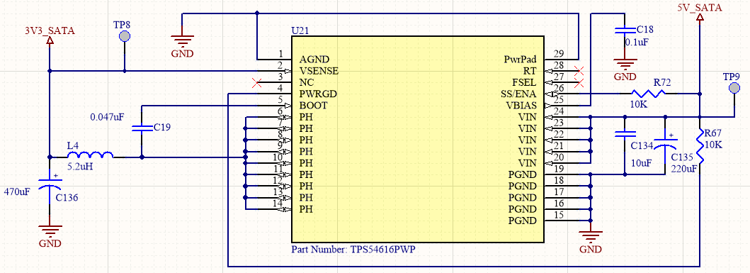
In my design, I need to generate a 3V3 power supply from 5V voltage. As the devices in the design request a current greater than 2A I decided to use the TPS54616, which provides 3V3 and at least 6A of current.
The figure shows my configuration, as shown in the datasheet.
The problem
When I connect my 5V power supply to the circuit, I only get 6mV at the output pin (PH) with this configuration.
The values of the components are in the range of values recommended by the datasheet:
- C19 (from BOOT to the output pin PH) must be in 0.022uF - 0.1uF range, so I decided to put 0.047uF.
These were my steps attempting to solve this problem:
- I have changed the value of C19 to other values (in the range above) --> still not working.
- Remove R72 from SS/ENA pin to 5Vdc. This will leave the SS/ENA pin open --> still not working.
- Instead of R72, I have used a slow-start capacitor, but nothing changes --> still not working.
- If I remove C19 (BOOT capacitor) from the circuit, I get 3V3 volts at the output pin --> seems to be working.
So if R72 and C19 are removed from the circuit, I get the desired voltage at the output.
- Why is this happening? Datasheet says that a capacitor needs to be connected between BOOT and PH pins.
- In a particular situation, the inductor (output filter) started to make noise, and after 1-2 seconds my power supply stopped feeding the circuit (as a protection).
- Which are the correct values for the components in the case of TPS54616?
- What is the correct schematic to make the circuit work?
Kind Regards
Salvador
