This thread has been locked.

If you have a related question, please click the "Ask a related question" button in the top right corner. The newly created question will be automatically linked to this question.

BQ76940: Testing for CELLBAL

Part Number: BQ76940

Good day,

I'd like to test if cell balancing activates properly when I write to the corresponding CELLBAL register. I only have a multimeter right now, so I'd like to ask what pins (and referenced where) I can measure voltages from and the corresponding expected value

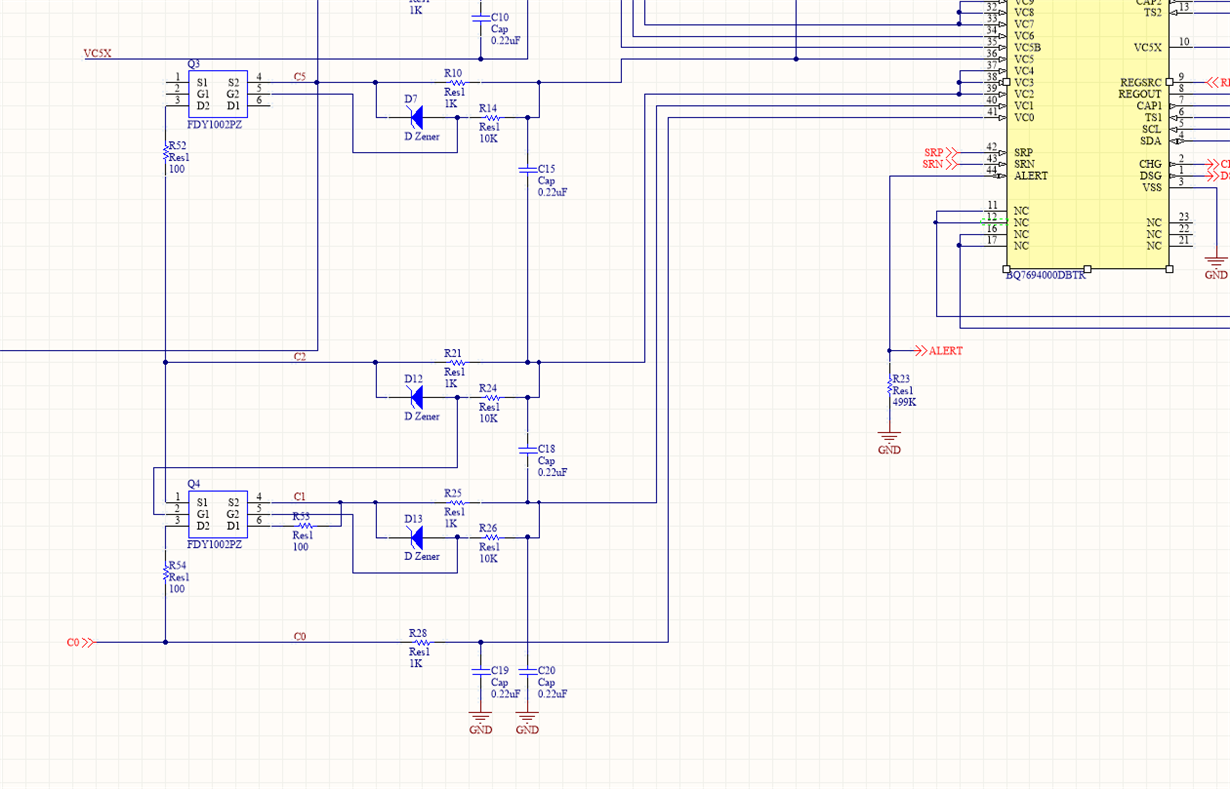
Here's a part of my schematic: For example if I wrote 0x01 to CELLBAL1, should I be looking for some value from VC1 to GND?


Thank you very much,

Robert

  • Hi Robert,

    In addition to the description of cell balance operation in http://www.ti.com/lit/pdf/slua749 , see also figure 5 of http://www.ti.com/lit/pdf/slua775 .  Looking at the voltage across R54, R52, etc can be a good way to see operation, but when using resistive cell simulators to power the cell the voltage on the cell can collapse reducing the gate voltage to the FET and the voltage on R54 may not change significantly.  It may be suitable to look across your cell simulator resistor for a change, or at the voltage of VC1 either with respect to VC0 or GND.

  • Thanks for the reply. And yes, I am using resistive cell simulators now. I've got 9 in series, at about 3.1V each. I'm not seeing any voltage at R54 when I write 0x11 to CELLBAL1. Measuring VC1 with respect to GND, I get about 2.2V.

    Also, I can't seem to open your first link.


  • Hi Robert,

    It sounds like the cell balance is coming on but does not power the external FET.

    The comma got attached to the link, see http://www.ti.com/lit/pdf/slua749 I will try to edit above.

  • I checked some voltages (when cell balancing is on):

    I measured Vgs = Voltage across D13 = -1.0V to -1.5V (fluctuating) Isn't this enough to power the FDY1002PZ P-Channel FET?

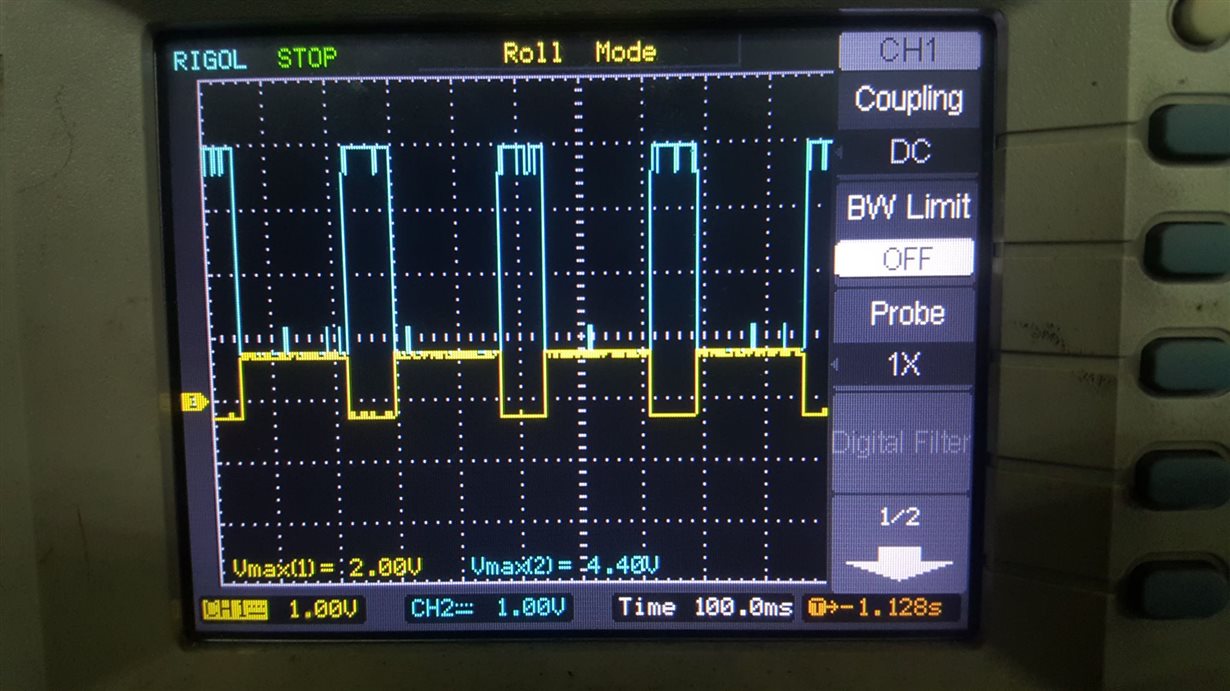
    And here I looked at VC0 (yellow) and VC1 (blue):

    And I noticed it is not quite the same as in Figure 5 in http://www.ti.com/lit/an/slua775/slua775.pdf

    Any ideas on why I can't seem to turn on the external FETs?

  • Hi Robert,

    I'm not sure which waveforms you are looking at.  It seems odd that any go below GND.  I would seem you should have sufficient gate voltage to turn on the Pch FET.  You might be sure the FET is working and properly soldered.  You will have to find what is wrong.

  • Hello,

    The issue might be because of broken external FETs; because I just replaced my FETs and I am now getting a voltage (about 1V, fluctuating)  across R54 when cell balancing is on. What is the expected voltage across it while the cell balancing is on?

  • Hi Robert,

    If you have a low impedance source for C1 with respect to Battery- and C0, when you balance VC0 and VC1 should take on about 1/2 the C1 voltage.  If this is sufficient to completely turn on the FET, R54 should be approximately the C1 voltage when on. 

    If you have a resistor divider for cell voltages, R54 will be in parallel with the bottom cell simulation resistor and the voltage will typically fall off until the FET starts to turn off.  In this situation the voltage can vary unusually.  Small cell simulation resistors help but they get hot.