This thread has been locked.

If you have a related question, please click the "Ask a related question" button in the top right corner. The newly created question will be automatically linked to this question.

UCC256302: 120W power supply - No load problem

Part Number: UCC256302

Hi,

we use the UCC256302 controller in 120W power supply.

Input = 230VAC + pfc stage

Output = 80VDC, 1.5A

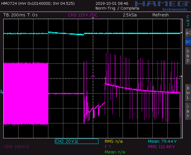
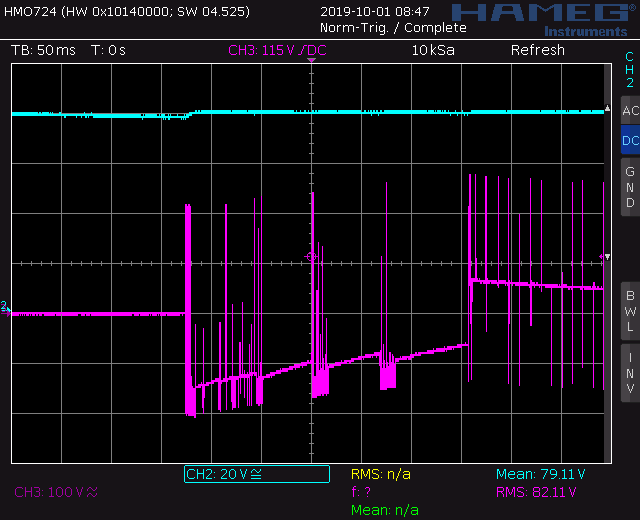
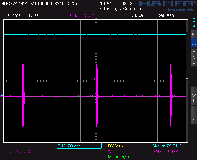
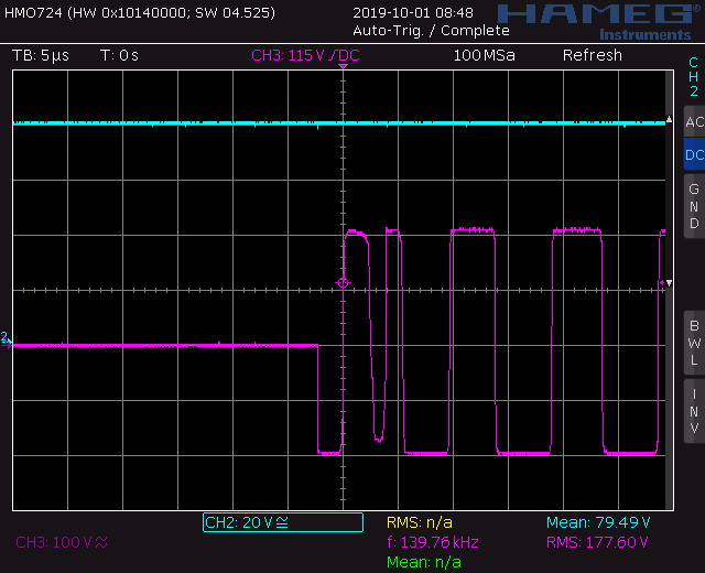
We are experiencing some problems with no load condition: the controller seems to turn off e the output is not regulated anymore. 

From similar threads in the forum we read that this kind of problem could be addressed to VCC going down when the burst period is too large.

In fact, when the burst period becames larger and larger, the VCC falls around 12,3V. 

We tried to increase slighty VCR signal but when we noticed some benefit, VCR was larger than 6V.

We tried also to increase VCC cap but it had not great effect.

Do you have any tips to solve this problem?

Many thanks,

Francesco.

  • Hi Francesco,

    I would suggest decreasing the resistance between LL/SS and gnd. This should move the burst mode threshold lower and make the converter burst more often and replenish the VCC cap more frequently. 

    Best Regards,

    Ben Lough

  • Hi Ben,

    thank you for the tip, it helps. The LLC stage is quite stable with no load.

    Now, testing the no load condition, we see this behavior of transient from full to no load.

    (Blue = Output voltage, Pink = Lower Mosfet VDS)

    After this transition, that lasts 300ms, burst mode is entered. 

    Do you have any suggestion to limit this transient condition?

    In addition, if we zoom the burst, we see this:

    Do you have an idea of the reason for such behavior? Is it correct?

    Many thanks,

    Francesco.

  • Hi Francesco,

    The controller will stop switching when going from heavy load to no load. This is to limit the max overshoot in the output voltage. The switching pattern when the converter resumes switching looks interesting but I would say it is likely the result of the low sampling rate of the scope in the first two plots. The third image shows the converter operating in burst mode. It looks normal. The fourth image shows the high side gate is slightly delayed in turning on which results in the switch node resonating back towards primary ground. This can happen if the controller misses slew rate detection. You could try minimizing any snubber capacitance that is on the switch node, reducing the MOSFET gate resistance or reducing the magnetizing inductance slightly to help improve the slew rate detection reliability.

    Best Regards,

    Ben Lough

  • Hi Ben,

    sorry for this late answer, i was stuck in another project.

    Thank you for the precise explanation.

    I will try to optimize the slew rate detection.

    However the no load problem is resolved so I mark the thread as resolved.

    Many thanks,

    Francesco.