This thread has been locked.

If you have a related question, please click the "Ask a related question" button in the top right corner. The newly created question will be automatically linked to this question.

TPS3430: Watchdog functionality not working as expected

Part Number: TPS3430

Hi....

One of my customer is using TPS3430 in their project. Refer below schematic.

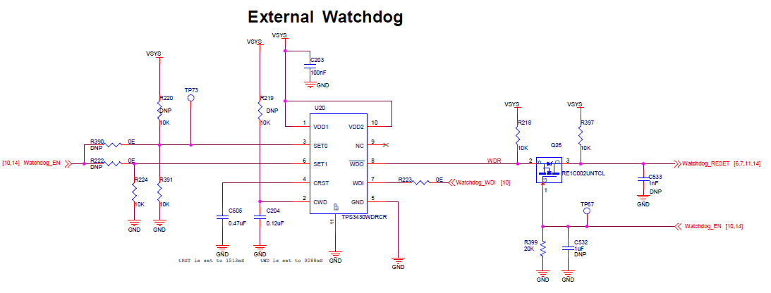
Customer has manufactured pilot batch of 100 boards and they have observed that most of the devices are rebooting at random time. During debug process they observed that watchdog output goes low even though WDI input is given to reset the counter.

 They are using watchdog in a window mode. As per capacitor values of CRST and CWD pins; Trst time is approx. 1.5 sec and watchdog counter time is approx. 9 Sec. They initially provided WDI pulse at interval of 5 seconds and with that devices are rebooting then they reduced this time to 1.6 seconds but with that also device is rebooting, and device reboot is random in nature.    

Please help resolving the issue, need details at what interval WDI input should be to avoid random reset?

Mitesh

  • Mitesh,

    With SET0=0, SET1=0, and C_CWD = 0.12uF

    I calculate upper boundary min = 7.94 s, typ = 9.343 s, max = 10.744 s

    lower boundary min = 0.99 s, typ = 1.1678 s, max = 1.343 s

    Please confirm that a rising pulse is arriving on WDI between 1.343 s and 7.94 s. What is the frequency and duty cycle for your WDI pulse?

  • Hello, 

    We provided WDI pulse to watchdog on every 5 seconds initially. As we observed the issue - we reduced the time to 1.6 seconds. But issue still persist. We observed the scenario on oscilloscope.   

    Please suggest if you need more information to resolve the issue. 

    Thanks,

    Pavan

  • Michael ,


    Can you help on inputs shared by Pavan? He is the user for this device.

    As he mentioned he has tried with watchdog reset at every 5 second, problem not resolved so gradually reduced to 1.6 seconds but issue still persists.

    What is the expected watchdog input pulse width?

    Mitesh

  • Mitesh,

    Please confirm there is a falling edge on WDI pin within the lower and upper boundary. The minimum pulse duration is 50ns on WDI. Can you provide a scope capture of WDI and WDO? Because the reboot is random in nature, this may suggest a soldering or board issue. Please also confirm the SET pin logic levels are in the correct logic state with the oscilloscope. I will try to get this resolved ASAP

  • hi Micheal,

    Thanks for the inputs. I will surely share the OSC outputs.

    Can you please help me with below queries

    1. “VSYS” can range from 3.0V to 4.3V. The “Watchdog_EN” signal is generated from GPIO bank. The GPIO is operating on 3.0V range. Will this affect the watchdog WDI signal ?
          Datasheet describes the pulse to be high-to-low pulse for WDI. Datasheet downloaded from www.ti.com/.../tps3430.pdf.
    2. WDI can be minimum of 50ns as per datasheet. We are supplying and 800ms pulse. It should be sufficient. But still we have seen WDO getting triggered.
    3. Is there any limitation on duty cycle of the pulse?

  • 1. The Watchdog_EN inputs into the SET pins which do not depend on VDD voltage level. The VIL and VIH of the SET pins are 0.25V and 0.8V respectively. The Watchdog_EN also controls the output FET on WDO so they may be one cause of issue.

    2. The WDO output is controlled by WDI inputs and SET inputs. The scope capture should show what is happening on WDI, SET0, SET1.

    3. There is no limitation of the duty cycle so long as the pulse width is met, there is a falling edge within the lower and upper boundary, and no falling edge in the lower boundary since that will trigger an early timing fault.

    The oscilloscope will be helpful to see the logic levels on the WDI, SET0 and SET1. Also I recommend removing the FET at /WDO and monitoring /WDO directly.

  • I have not heard any updates on this issue. Has this item been resolved? Please let me know if further assistance is needed. Thanks