This thread has been locked.

If you have a related question, please click the "Ask a related question" button in the top right corner. The newly created question will be automatically linked to this question.

TPS7A7001: Selection of output ceramic capacitor

Part Number: TPS7A7001

Hi All,

I have a large customer that needs help selecting a ceramic capacitor for the output.

Please see below.

Thanks,

Regards,

Joe

From Customer:

I’m having trouble merging the required output capacitor ESR with the real world capacitor ESR graph for the TI TPS7A7001DDA LDO


The TI part wants from 30m-ohm to 1 milli-ohm and a max of 1 ohm depending on load current(Figure 2 of datasheet). Since we may have one or two pieces of these regulators we cannot guarantee that we will be above 50 mA at all times especially during reset and boot so I look at the output capacitor graph and see that it wants 30milli-ohm of ESR at zero current.


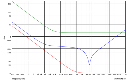
But a typical ceramic capacitor has a ESR graph that is not flat  depending on frequency so which frequency do I look at to see if we are meeting the required specification?


I looked at the TI eval board schematic for this part and it shows an 0805 10u X7R cap on the output. That has the same curve as well but does get above 1 ohm at about 400 Hz which breaks the max upper limit requirement. Our concern with 0805 capacitors is that they are hard to get as the market wants us to use 0402 or 0201 caps which make the ESR even lower not to mention voltage bias effects have an even lower actual capacitance but I’m more confused about the ESR graph and how to apply. I thinking 0603 might be a good compromise.


Some LDO’s say they are made for ceramic output caps and have a 0 ohm lower limit. Is the TPS7A7001DDA designed for ceramic output caps?


We have lots of downstream capacitors as well in the 10 uf range but there is some trace impedance to get to them and we have the ability to add ferrites in series if needed for noise and maybe to help isolate too much extra capacitor ESR from the LDO output.


Even the output ESR graph for the TPS79630 LDO isn’t clear on the lower limit. The graph stops at 10 milli-ohm. Not sure what happens below there.


We chose the TPS7A7001DDA for price reasons. If there is a better part that can get the heat out we would be happy to consider it. Our current can be quite high maybe 0.5 Amp depending on wifi transmit bursts for instance.


Can we use ceramic output capacitors for TPS7A7001 and what size and value is safe?


  • Hello Joe,

    I would be happy to help. 

    Equivalent models of capacitors - especially non ceramic capacitors - are complex.  Equivalent models for capacitors can be found on the manufacturer websites, and typically involve some form of ladder network to model the impedance correctly.  Even X7R ceramic capacitors are now being modeled as a ladder network on some manufacturer websites, although a simple series ESR - ESL - C model can be a good approximation.  The TI datasheet gives a good first estimate at whether your design will be stable, and this guidance is sufficient to evaluate the stability of most designs.  For those designs which involve more complex loads, I recommend the customer build a model of their loads - using manufacturer capacitor models - to evaluate how close they are to meeting the stability criteria.  Let me explain. 

    It is important to note that the recommendations are for stability.  So the frequency of concern is where the internal loop gain crosses zero, or the internal bandwidth of the component.  There are many factors which affect the bandwidth, so a range of frequencies are involved.  We can start by saying that very low frequencies are not an issue, and very high frequencies are not a concern, because the bandwidth of the part is somewhere in the middle.

    For the TPS7A7001, the datasheet specifies 4.7uF to 47uF capacitance without a feedforward capacitor, and 47uF to 200uF capacitance with a feedforward capacitor, as the range of stability.  As shown in figure 1 and 2, the ESR for most loads can range from 1m ohm (ceramic or polymer type capacitors) to 1 ohm (electrolytic capacitors) and in between (tantalum capacitors).  This load includes the setpoint resistors, so that may help your customer as no load is truly "0 amps". 

    Once you have this information you can plot the equivalent impedance of the complex load across frequency, and check that it does not go outside of the range of stability.  An example simulation is provided below of a different LDO but using the same concept.  The upper impedance is dictated by the green line and the lower impedance is the red line.  The blue line is the impedance of a parallel combination of an electrolytic and ceramic capacitor, using manufacturer capacitor models.  At the high end the blue line goes above the green line, but since this is extremely high frequency - well above the bandwidth of the part - I know this part is stable with this load.  In this way your customer can evaluate their complex load against the TI datasheet.

    Thanks,

    - Stephen

  • Hi Joe,

    For reference, here is the impedance curves with the TPS7A7001 limits and two capacitors.
    The first plot shows an 0805, 10V, X7R, ceramic 10uF capacitor using a manufacturer online tool model.
    The second plot shows an 0805, X5R, ceramic 10uF capacitor impedance across frequency from the manufacturer online tool.
    A model did not exist of an X5R but this plot is still valuable for review.

    The first plot is stable because the blue line is within the limits, within the bandwidth of the LDO.

    The second plot is stable by visual inspection with the limits of the first plot.
    So the EVM should be stable, at least at room temperature, which is where this data was simulated at.

    Thanks,

    - Stephen

  • Hi Stephen,

    Thanks for the quick response.

    If I understand you correctly, the green and red line are the maximum and minimum complex impedances that can be connected to the LDO and still maintain stability. You determined these lines by using the min/max capacitance and ESR stated in the datasheet.

    Correct?

    Thanks,

    Regards,

    Joe

  • Hi Joe,

    That's exactly what I did.
    If I were the customer I would gather models for my loads and repeat this exercise.
    I would include tolerance across temperature and any other factors the customer would deem appropriate.

    Any modern SPICE simulator can do this analysis in less than 1 second after the models are built.

    Thanks,

    - Stephen