This thread has been locked.

If you have a related question, please click the "Ask a related question" button in the top right corner. The newly created question will be automatically linked to this question.

TPS54618: TPS54618 SW-Node shorted to GND after power-cycles

Part Number: TPS54618

Hello,

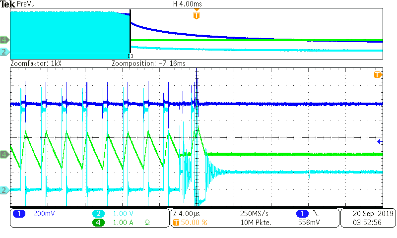
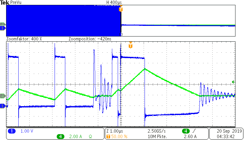
i have a circuit with this DCDC-Converter for an output voltage of 1,0V. I have also many other circuits with higher output-voltages ( 1V8, 2V5, 3V3 ) all from a VIN = 5,1V. Only some circuits with the 1V0 output make troubles ( after many power-cycles the switch-node is shorted to ground -> internal BOT-FET is shorted ). The circuit of the 1V0-Converter uses a 0,8uH-Inductor, all other circuits uses a 3,3uH-Inductor. I have made many measurements at the power-up and power-down ( plug-off ). Sometimes at the plug-off-state, i can see a huge increase of the inductor-current, although the controller has been disabled with the Enable-Pin. I have attached the circuit and this measurement.

Have anybody an idea related to this problem?

I use the Track-Pin for voltage-tracking. Also an external synchronisation is used, but  i  have tried it without this synchronisation and this problem also occurs.

The load of the 1V0 voltage is about 1-2 A.

Best regards

Gerald

  • Hello Gerald,

    Can you explain a bit more what you mean by power-down (plug-off)? It doesn't seem on the second graph that the output is disabled.

    To help you better, Could you share the Layout of your system here?

    How did you come up with the BOM of your system? 

    Thank you! 

    Regards,

    Dorian

  • Hello Dorian,

    thank you for you fast answer!

    From older measurements, which i have attached, you can see how the output voltage will fall after power-down.
    CH1...1,0V Output
    CH2...SW-Node
    CH4...Inductor-Current

    In this following picture, you can see the state if the Enable-Pin has been pulled low to disable the controller. You see the last few switching-cycles, but the enable-pin is set to low at about -3us before triggertime:
    CH1...SW-Node
    CH4...Inductor-Current

    Be aware that this pictures are not the same triggerevents, but the same pcb and test-setup.

    BOM:
    I have made calculations for a max. load of 6A. Input-Voltage of 5,1V and a synchronisation-clock of 500kHz. Because i have more such DCDC-converters for 1V8, 2V5 and 3V3, the SS/TR-Pin is used for tracking the 3V3 for a simultaneous start-up.

  • Anybody an idea or tips relating to this problem?

  • Hello Gerald,

    I think here we need to focus on enable signal itself.

    The raise of the inductor current is induced because the switching still occurs.

    Could you tell me what is the use of D19 ?

    As you can see in topic 7.3.7 of Datasheet (Enable and Adjusting Undervoltage Lockout), we don't recommend the use of any diode. I think it might bias the voltage that EN sees at its input.

    Were you using this diode on other TPS54618 in your system?

    Thank you very much!

    Best Regards,

    Dorian 

  • Hi Gerald,

    I haven't heard back from you.

    Did you make some progress? 

    Do you have answer to the questions on the previous post?

    Do you have any further questions?

    Thank you very much!

    Regards,

    Dorian