This thread has been locked.

If you have a related question, please click the "Ask a related question" button in the top right corner. The newly created question will be automatically linked to this question.

BQ34Z100-G1: SOC latency effect

Part Number: BQ34Z100-G1
Other Parts Discussed in Thread: GPCCHEM

Hello,

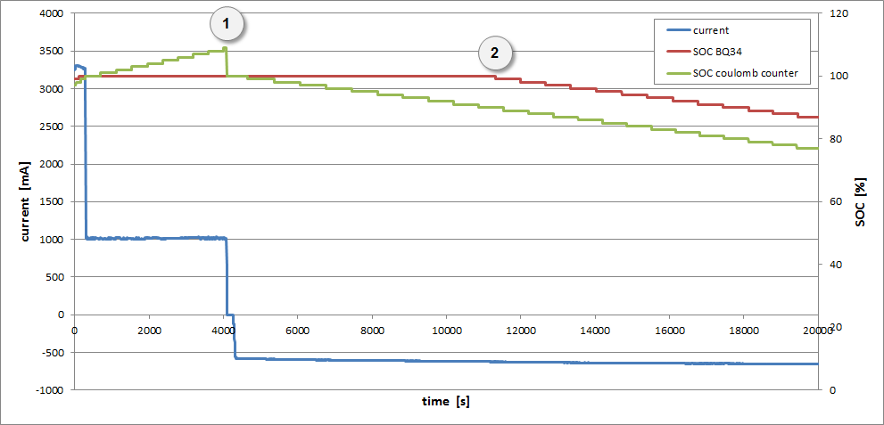
I'm using the BQ34Z100-G1 for monitoring a NiMH battery pack.

During the charging phase, the charger apply a kind of trickle charge for a copula of hours after the SOC has reached the 100% value. In the following discharge phase I see the SOC level remains at 100% value for a long time (few hours). Such a "latency" in the SOC update during discharge creates a big error in the SOC estimation.

How is it possible to increase the "reactivity" of BQ34Z100-G1 at beginning of the discharge phase?

Thank you for any support and best regards.

Matteo

P.S. In attachment you can find the configuration file190918_configurazione_NiMH_paccoX_ver0002.gg.csv

  • Hi Matteo,

    First you need to obtain the correct chem ID for the battery. In the absence of that, your gauging can be off. Please perform the chem ID match using GPCCHEM.

  • The chem ID has been poperly selected: I'm using the cell BK1100FHU, wich is included into the official chem ID database.

    Matteo

  • Hi Matteo,

    Please disable RELAX_SMOOTH_OK in pack configuration c, then send IT enable and run your cycle.

  • Hi Batt,

    thank you for your suggestion.

    I've implemented it, but it still doesn't work. The below graph can better show the behaviour:

    The blue curve represents the battery current and it is possible to indetify these phases:

    • charge at 3A up to SOC=100%
    • overcharge at 1A for 1 hour
    • relax for a few minutes
    • discharge at 600-700mA for some hours

    The red curve represents the SOC level provided by the BQ34Z100-G1. The green curve is a SOC estimation simply based on a "coulomb counter" calculation.

    As you can see, during the overcharge phase, the BQ34 SOC value is fixed at 100%, while the coulomb counter detects the battery overcharge level.

    When the overcharge phase is finished (point 1 in the figure), the coulomb counter value has been reset to the 100% value before to stat the discharge phase.

    When the discharge phase starts, the coulomb counter SOC properly point out a decrease in the SOC level, but the BQ34 SOC remains still fixed at 100% value. When the coulomb counter value has reached a reduction equals to the previous overcharge level (point 2 in the figure), the BQ34 SOC starts to decrease.

    It seems internally the BQ34Z100-G1 has incremented the SOC level by the same mechanism of the coulomb counter. Is that true?

    In any case, such an effect is misleading because the SOC level provided by the BQ34Z100-G1 is not correct. Is there any other way to avoid this?

    Thank you very much and best regards

    Matteo

  • Hi Matteo,

    There are 2 cases here, one is the overcharge and the second is the fact that smoothing is enabled. You are using a load select of 3, however when the dsg starts the gauge is going to use avg I last run for the first capacity simulation. This is set to -2222mA, therefore the gauge is going to hold that capacity in true capacity and check to see at the first grid point during dsg if that is correct. If it's not, then it will smooth out the drop to the actual drop and reduce capacity from that point onwards.

    I would suggest plotting the ratio of true RM and true FCC to get a clear picture of what the gauge is really seeing here.