Other Parts Discussed in Thread: LM5180, , TPS2662
We have a prototype where we are connecting TPS2662 output to standard flyback configuration using LM5180 with EMI filter (for isolated 13.5V output), as shown in the schematics below.
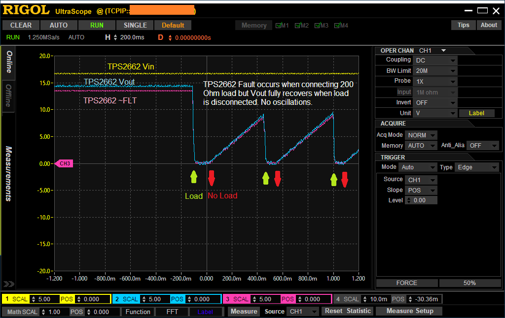
The output of the TPS2662 (which is the input of LM5180) is oscillating at 200 msec (charging and discharging cycles, with ppk = 2.16V around 5.75V). The supply voltage is 12.6V from batteries. The waveforms are shown below.
What changes should we make to the LM5180 circuits below to resolve the instability issues?
Also, the output of the Flyback is 14.9V at no load, but it goes down to 6.5V if we connect 200 Ohm dummy load.
Please let me know if you'd need further information (PCB layout or settings used in TI design tools).
Thank you.
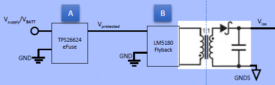
LM5180-Q1 Flayback Schematic (Standard)

TPS2662 Protection Schematics (Standard)

Waveforms (@500 msec/div)

Waveforms (@50 msec/div)