Other Parts Discussed in Thread: LMZM23601EVM
I'm working on a space-constrained design with limited same-layer area for thermally sinking the 5V fixed version of the LMZM23600. We've now produced several dozen boards, each with 2 modules, and on ~10% of them, one or both of the modules run extremely hot, sometimes to the point of triggering thermal shutdown.
We're drawing nominally 160-170 mA (at 5V) from each module, and nominally supplying 35-50 mA at 28V, for efficiencies around 80% and on-module dissipations around 200 mW. We're nominally seeing ~20C temperature rises above ambient, for thermal resistances of 80-100 C/W, all of which feel reasonable and in spec. On the failing boards, we see no change in output current but dramatic increases in input current, 75-100 mA at 28 V, for dramatically lower efficiencies which heat the modules up much more (75-130 C above ambient). This doesn't happen on first power on but worsens over time, with failures occurring within ~10 hours of operation. Despite all of this the modules have no visual evidence of damage (other than darkened conformal coat due to the heat) and seem to be regulating effectively (until they overheat and trip their thermal protection), and actively cooling a module with compressed air allows it to continue functioning nominally. What could be causing this and what are useful tests to perform?
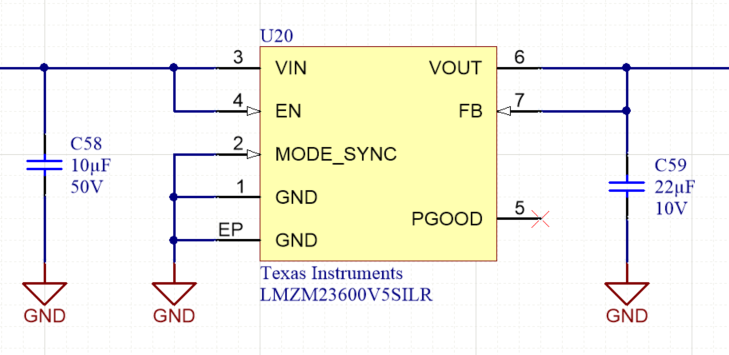
SCH:
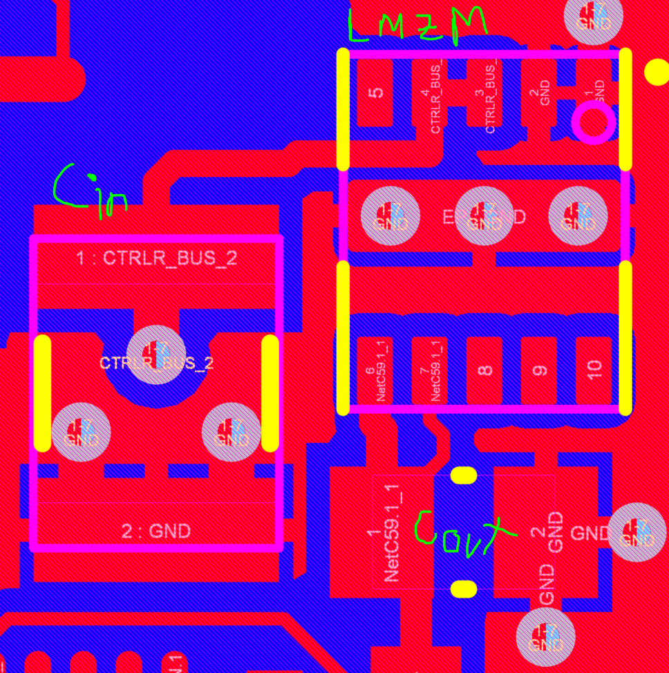
PCB: