This thread has been locked.

If you have a related question, please click the "Ask a related question" button in the top right corner. The newly created question will be automatically linked to this question.

LM3421: SEPIC circuit

Part Number: LM3421

Hi,

Could you please check the SEPIC application circuit in Datasheet? I believe the L2 direction is incorrect.  Is it correct direction?

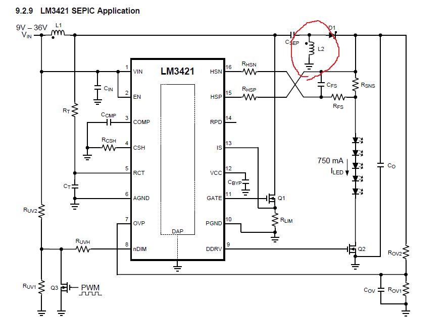
Usually, SEPIC circuit seems to be as below.

Regards,
Nagata.

  • Hello,

    You are correct and that's a typo on the inductor.  The DOT should be on the ground side for coupled inductor design.

    Thanks Tuan

  • Hi, Tuan,

    Thank you for your support. Could you please check for buck-boost reference schematic?

    1. Cathode of LED connects to Vin (with red circle). Is it connected to GND? if not, Why does it connect to Vin?

    2. What does Q2 useful for? (what is the meaning of Q2? )

    Regards,
    Nagata.

  • Hello Nagata,

    Tuan is out of office so I'll reply.

    1)  This is a buck-boost that is reference to Vin, sometimes called a boost to battery.  Basically the LM3421 circuit is a boost converter but the load, LED string, is connected between the boost voltage (ANODE) and Vin (CATHODE).  This allows the input voltage to be both higher and lower than the output voltage.  One limitation becomes the overall voltage of Vin and Vled.  If Vin is 20V and Vled is 20V the IC sees 40V (which would be the boost voltage with respect to GND.  In the case where the bottom (CATHODE) of the LED stack went to GND and the top (ANODE) went to Vin then it would be considered a boost converter.

    2)  Q2 is basically a resistor divider that allows the translation of the LED string voltage to be referenced to ground.  Rov2 is across the LED string, with an added diode drop from Q2.  Rov1 is referenced to ground.  The current in Rov2 and Rov1 is basically the same so it can be considered a resistor divider that allows the LED string to float on Vin.  This translates the LED string voltage through the divider ratio to ground.  The equations in the datasheet will show this, 9.2.2.2.12 for the example of your picture.  This is necessary because the CATHODE connection of the LED string is not referenced to GND, it is referenced to Vin when can change.

    Best Regards,