This thread has been locked.

If you have a related question, please click the "Ask a related question" button in the top right corner. The newly created question will be automatically linked to this question.

LM5155: Connecting CS and COMP to PGND

Part Number: LM5155

Hello,

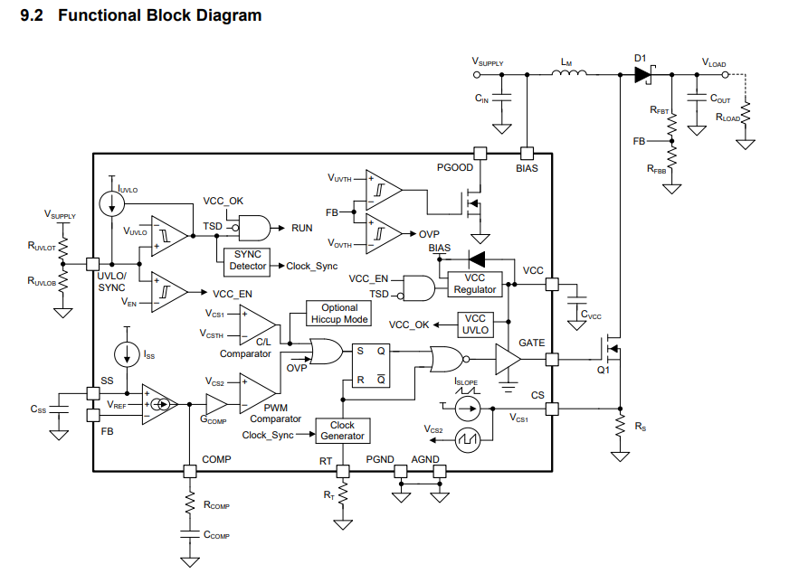
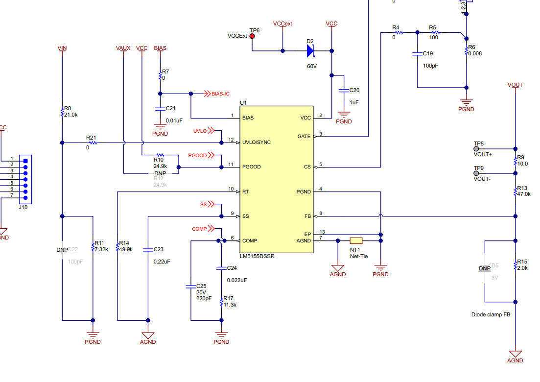
The datasheet for this device shows the CS and COMP components being grounded at PGND rather than AGND. Is there a reason for this? Is it just layout convenience?

Thanks,

Michael

  • Hi Michael,

    Thank you for considering LM5155. Could you provide the information where you see in the datasheet for the CS and COMP ground connection? 

    In the functional block diagram below, the PGND and AGND are tied togather.

    Generally, PGND and AGND are electrically the same. However, we separate them for noise immunity purpose. I would tie the COMP to AGND to ensure a clean COMP signal. But the PGND and AGND are tied together at some point with a net-tie in your layout.

    Thanks,

    Yinsong

  • Hi Yinsong,

    My apologies, it's the EVM user guide not the datasheet that shows it.

    So I will connect COMP to AGND, but what about CS? Should that be AGND as well?

    Thanks,

    Michael

  • Hi Michael,

    Sorry but I'm not quite sure what you mean by connect CS to AGND. CS is the current sense which directly get current from the sensing resistor of the power stage. If you are talking about the ground of the sensing resistor, that has to be connected to PGND since it is part of the power loop. And to help filter out the leading spike noise of CS, you can add the RC filter (R5, C19 in the EVM schematics), which is also mentioned in the datasheet.

    Thanks,

    Yinsong