This thread has been locked.

If you have a related question, please click the "Ask a related question" button in the top right corner. The newly created question will be automatically linked to this question.

TPS73601-EP: tps73601 is locked to a unexpected output

Part Number: TPS73601-EP

Hi, all!

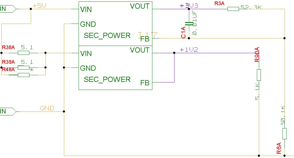
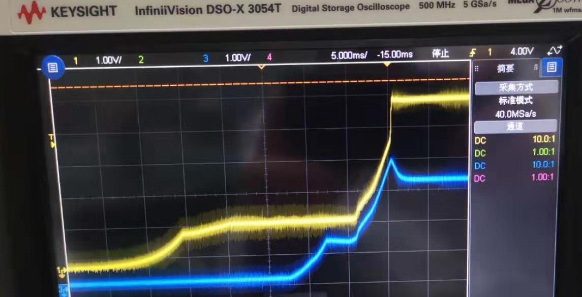
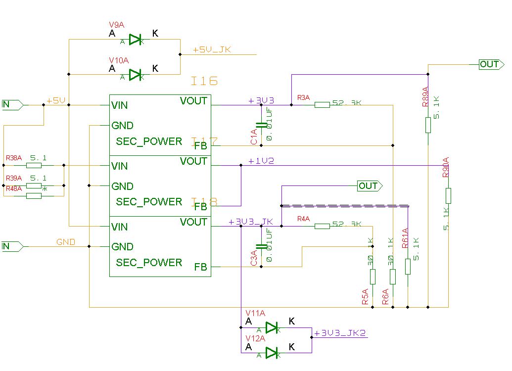
We used two LDOs, TPS70601DRBR, to provide the 3.3V and 1.2V supply for an Microsemi FPGA. The input of TPS70601DRBR is 5V. When we power up the circuit, it becomes so weird that the TPS70601DRBR which generates 1.2V sometimes cannot raise the output to the expected 1.2V.  In this case, the output of the TPS70601DRBR is locked to 0.5V and therefore the FPGA fails to boot. However, this never happens at the 3.3V output  TPS70601DRBR.

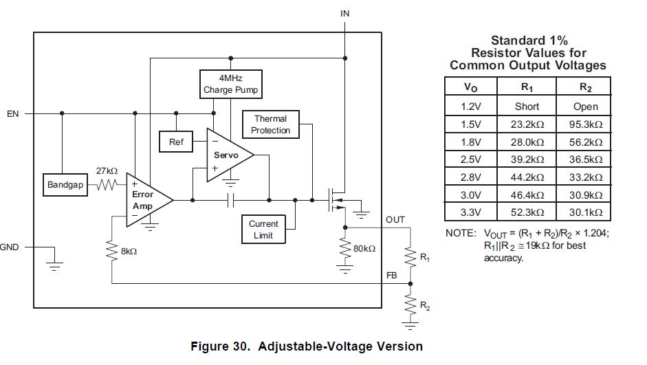
We have followed the recommended design demo in the datasheet of TPS70601DRBR and currently feel few clues of what is the reason for this problem.  We guess if this problem results from few capacitors at the input end of this LDO, or  the resistors labelled as R38A or R39A may have large current when the output of the LDO starts to climb. 

We sincerely welcome any helps from TI.

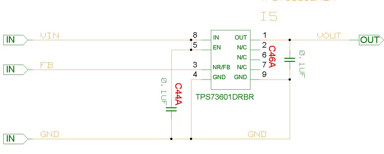
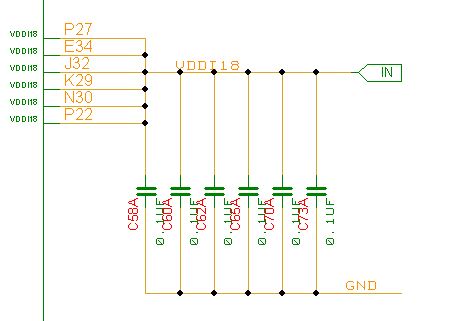
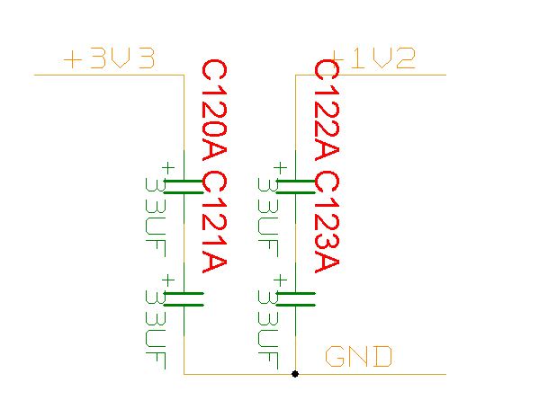
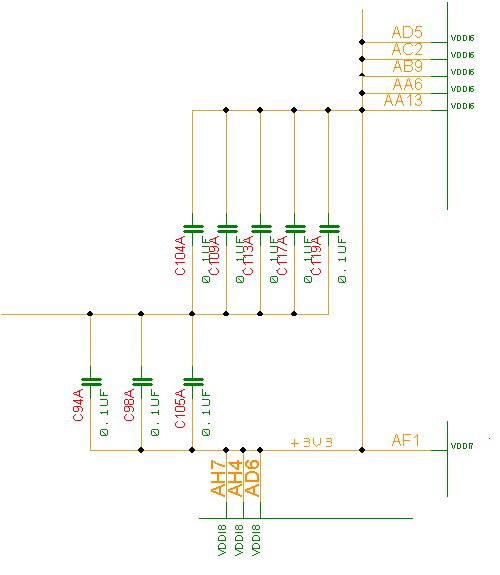
Please find the schematic of our design as follows

  • To confirm,

    You state the device as the TPS70601DRBR do you mean the TPS73601DRBR?

    This sounds like the output is pulling too much current as:

    Thanks,

    Daniel

  • Hi, Deniel!

    Thanks for your kind response. 

    First, the LDO is TPS73601. Earlier post was a spelling mistake.

    Second,  we see in the datesheet that too much current would cause LDO protected. If it happens, can the protection be automatically released without power cycle? e.g.  the current later becomes smaller. 

    Third, we looked into the section 6.5 Electrical Characteristics of the datasheet. Here the input voltage is noted as the following image shows. We do not understand the meaning of (2). Can the lock be released later and work normal if the Vin reaches higher than 1.6V. Who will "Disable the device before powering down Vin"? Does it mean the LDO will disable itself or the EN pin should be controlled to be low externally.

    Thanks for your patience!

    Best regards,

    SC

  • Hey SC,

    Generally, yes, foldback current implies you don't need to power cycle the part, however I imagine there may be issues with keeping on whatever you are powering.

    It sounds like the part isn't rated for the load.

    Note two is talking about how the input voltage must be above 1.6 V to be able to properly supply an output voltage of 1.6 V.

    The output should be disabled until the VIN reaches 1.6 V in order to avoid output voltage overshoots.

    Thanks,

    Daniel

  • Hi, Daniel!

    We have tested the 1V2 and also another 3V3 output on the board. We found the output of 73601 may come to a transient  peak voltage greater than the expected. The captured image of 3V3 power up  is attached. with 5V yellow  and 3V3 blue.  You can  find the blue voltage may reach 4V.

    What is the reason of the output greater than 3V3 and is it normal?

    Best regards,

    SC

  • Hey SC,

    While slightly abnormal, its quite possible that the load that the line is supplying is drawing current at a nonlinear rate causing this overshoot and general nonlinearity in the start up.

    Figure 24 in the datasheet shows a typical start-up response, but note this is with a resistive load which is gradually increase over the increase in voltage. The shape of the start-up voltage will very much depend on what the load looks like.

    Thanks,

    Daniel

  • Hey, Daniel!

    The overshoot  is weird because we just use the 1V2 and 3V3 supplying with the VDD and VDDI for  FPGA Microsemi M2S150T.  Only decoupling capacitors are connected with these pins.

    Do you have some suggestions for the improvement?

    Regards,

    Shengchang

  • Hey, Daniel!

    The overshoot  is weird because we just use the 1V2 and 3V3 supplying with the VDD and VDDI for  FPGA Microsemi M2S150T.  Only decoupling capacitors are connected with these pins.

    Do you have some suggestions for the improvement?

    Regards,

    Shengchang

  • Hey Shengchang,

    Given the device does not have an active pull down, adding a small amount of load to the output will help with the output voltage overshoots.

    This is because the TPS73601-EP does not have an active pull down when the device goes too high.

    Thanks,

    Daniel

  • Hey, Daniel!

    I get your idea that  we need to add more resistors at the output and actually we have 5.1K pull-down  resistor tied to the 3V3 output. Do you have some recommended values if we reduce the resistance.

    Additionally, I have some questions on the resistors tied to FB pins labelled as R3A and R6A . For a 3V3 output, we learned the values from the P13, datasheet. I wonder whether the 52.3K and 30.1K are so large that the output current may become small. The small current will be more sensitive . Is it correct? Can we use other values of the resistors to increase the current?

    Best regards,

    SC

  • Hey SC,

    I might suggest pulling around 10 mA of current out and seeing if that works.

    I don't suggest changing the FB resistors as that can cause other issues (such as accuracy) with the part.

    Thanks,

    Daniel

  • Hey SC,

    Did this resolve itself?

    Thanks,

    Daniel