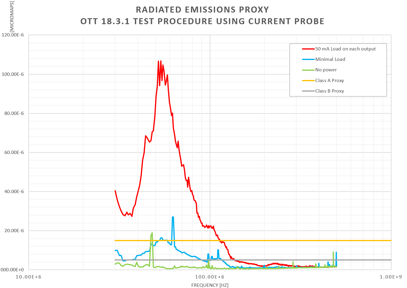
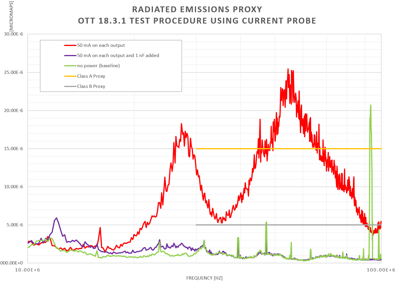
I'm looking for suggestions on why I am measuring high conducted emissions of my design using the LM5180. The worst peak is at 56 MHz.
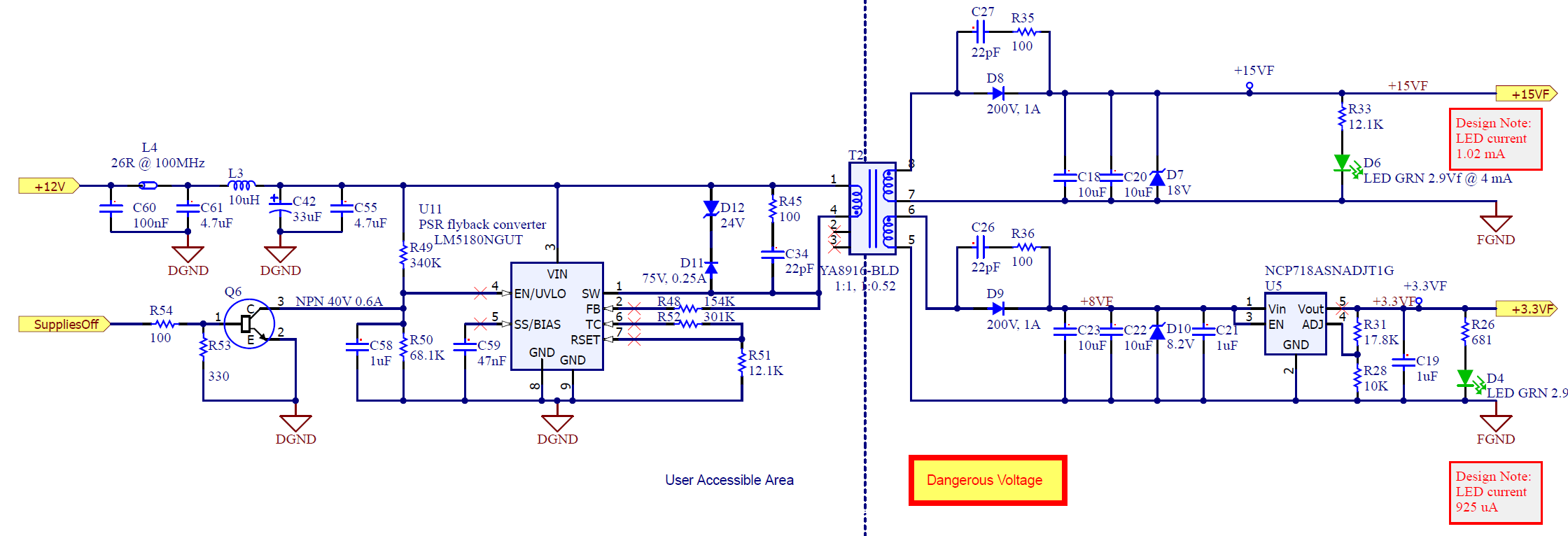
My design is based closely on the LM5180EVM-DUAL.
Reference: http://www.ti.com/lit/ug/snvu609a/snvu609a.pdf
Find, "EVM Schematic"
Here is my design. I made the -7.7 V positive instead.
| Designator | Description | Mfr | MfrPN | Digi-Key PN |
| U11 | 70-Vin PSR flyback converter with 100-V, 1.5-A integrated power MOSFET | Texas Instruments | LM5180QNGUTQ1 | 296-LM5180QNGUTQ1CT-ND |
| C42 | CAP ALUM 33UF 20% 50V RADIAL | Panasonic Electronic Components | ECA-1HM330 | P5180-ND |
| C59 | CAP CER 0.047UF 16V X7R 0603 | Samsung Electro-Mechanics | CL10B473KO8NNNC | 1276-2079-1-ND |
| C60 | CAP CER 0.1UF 50V X7R 0603 | Samsung Electro-Mechanics | CL10B104KB8NNNC | 1276-1000-1-ND |
| C18 | CAP CER 10UF 25V X5R 0805 | Samsung Electro-Mechanics | CL21A106KAFN3NE | 1276-2890-1-ND |
| C20 | CAP CER 10UF 25V X5R 0805 | Samsung Electro-Mechanics | CL21A106KAFN3NE | 1276-2890-1-ND |
| C22 | CAP CER 10UF 25V X5R 0805 | Samsung Electro-Mechanics | CL21A106KAFN3NE | 1276-2890-1-ND |
| C23 | CAP CER 10UF 25V X5R 0805 | Samsung Electro-Mechanics | CL21A106KAFN3NE | 1276-2890-1-ND |
| C19 | CAP CER 1UF 25V X5R 0603 | Samsung Electro-Mechanics | CL10A105KA8NNNC | 1276-1102-1-ND |
| C21 | CAP CER 1UF 25V X5R 0603 | Samsung Electro-Mechanics | CL10A105KA8NNNC | 1276-1102-1-ND |
| C58 | CAP CER 1UF 50V X5R 0603 | Samsung Electro-Mechanics | CL10A105KB8NNNC | 1276-1860-1-ND |
| C26 | CAP CER 22PF 50V C0G/NP0 0603 | Samsung Electro-Mechanics | CL10C220JB8NFNC | 1276-2228-1-ND |
| C27 | CAP CER 22PF 50V C0G/NP0 0603 | Samsung Electro-Mechanics | CL10C220JB8NFNC | 1276-2228-1-ND |
| C34 | CAP CER 22PF 50V C0G/NP0 0603 | Samsung Electro-Mechanics | CL10C220JB8NFNC | 1276-2228-1-ND |
| C55 | CAP CER 4.7UF 50V X5R 0805 | Murata Electronics | GRM21BR61H475KE51L | 490-10751-1-ND |
| C61 | CAP CER 4.7UF 50V X5R 0805 | Murata Electronics | GRM21BR61H475KE51L | 490-10751-1-ND |
| D8 | DIODE GEN PURP 200V 1A SOD123W | Taiwan Semiconductor Corporation | UF1DLWHRVG | UF1DLWHRVGCT-ND |
| D9 | DIODE GEN PURP 200V 1A SOD123W | Taiwan Semiconductor Corporation | UF1DLWHRVG | UF1DLWHRVGCT-ND |
| D11 | DIODE GEN PURP 75V 250MA SOD123 | Micro Commercial Co | 1N4448W-TP | 1N4448WTPMSCT-ND |
| D7 | DIODE ZENER 18V 365MW SOD123 | Nexperia USA Inc. | PDZ18BGWJ | 1727-7766-1-ND |
| D12 | DIODE ZENER 24V 1W DO214AC | Micro Commercial Co | SMAZ24-TP | SMAZ24-TPMSCT-ND |
| D10 | DIODE ZENER 8.2V 500MW SOD123F | Nexperia USA Inc. | NZH8V2B,115 | 1727-5080-1-ND |
| L4 | FERRITE BEAD 26 0603 1LN | Samsung Electro-Mechanics | CIS10P260AC | 1276-6354-1-ND |
| L3 | FIXED IND 10UH 1.76A 89 MOHM | Wurth Electronics Inc. | 74404043100A | 732-10757-1-ND |
| U5 | IC REG LIN POS ADJ 300MA TSOT23 | ON Semiconductor | NCP718ASNADJT1G | NCP718ASNADJT1GOSCT-ND |
| D4 | LED GREEN CLEAR 0603 | Wurth Electronics Inc. | 150060GS75000 | 732-4971-1-ND |
| D6 | LED GREEN CLEAR 0603 | Wurth Electronics Inc. | 150060GS75000 | 732-4971-1-ND |
| R54 | RES 100 1% 1/10W 0603 | Stackpole Electronics Inc. | RMCF0603FT100R | RMCF0603FT100RCT-ND |
| R35 | RES 100 1% 1/8W 0805 | Stackpole Electronics Inc. | RMCF0805FT100R | RMCF0805FT100RCT-ND |
| R36 | RES 100 1% 1/8W 0805 | Stackpole Electronics Inc. | RMCF0805FT100R | RMCF0805FT100RCT-ND |
| R45 | RES 100 1% 1/8W 0805 | Stackpole Electronics Inc. | RMCF0805FT100R | RMCF0805FT100RCT-ND |
| R28 | RES 10K 1% 1/10W 0603 | Panasonic Electronic Components | ERJ-3EKF1002V | P10.0KHCT-ND |
| R33 | RES 12.1K 1% 1/10W 0603 | Stackpole Electronics Inc. | RMCF0603FT12K1 | RMCF0603FT12K1CT-ND |
| R51 | RES 12.1K 1% 1/10W 0603 | Stackpole Electronics Inc. | RMCF0603FT12K1 | RMCF0603FT12K1CT-ND |
| R48 | RES 154K 1% 1/10W 0603 | Stackpole Electronics Inc. | RMCF0603FT154K | RMCF0603FT154KCT-ND |
| R31 | RES 17.8K 1% 1/10W 0603 | Stackpole Electronics Inc | RMCF0603FG17K8 | RMCF0603FG17K8CT-ND |
| R52 | RES 301K 1% 1/10W 0603 | Stackpole Electronics Inc. | RMCF0603FT301K | RMCF0603FT301KCT-ND |
| R53 | RES 330 1% 1/10W 0603 | Stackpole Electronics Inc. | RMCF0603FT330R | RMCF0603FT330RCT-ND |
| R49 | RES 340K 1% 1/10W 0603 | Yageo | RC0603FR-07340KL | 311-340KHRCT-ND |
| R50 | RES 68.1K 1% 1/10W 0603 | Stackpole Electronics Inc. | RMCF0603FT68K1 | RMCF0603FT68K1CT-ND |
| R26 | RES 681 1% 1/10W 0603 | Stackpole Electronics Inc. | RMCF0603FG681R | RMCF0603FG681RCT-ND |
| Q6 | TRANS NPN 40V 0.6A SOT23 | Micro Commercial Co | MMBT2222A-TP | MMBT2222ATPMSCT-ND |
| T2 | Transformer for LM5180 | Coilcraft | YA8916-BLD |
Does anything stand out as a problem? Is there a place I should look first to narrow it down? Anything I should remove or replace to try to reduce the conducted emissions?
I am measuring conducted emissions using a Rigol DSA 815 Spectrum Analyzer with a TekBox RF Current Monitoring Probe, TBCP1-200