This thread has been locked.

If you have a related question, please click the "Ask a related question" button in the top right corner. The newly created question will be automatically linked to this question.

UCD90160A: Cannot resequence after a TON_MAX fault

Part Number: UCD90160A

I cannot resequence my UCD90160A on my target board when a TON_MAX fault occurs.

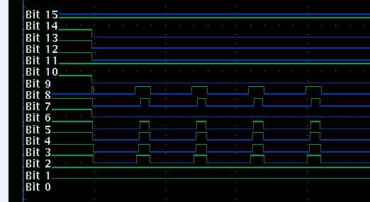
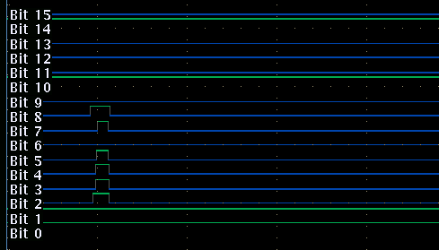
I came back on my 64 pins eval board with an UCD90160A to understand the problem on rail 13 P3V3 (bit 6 on the logic analyzer, bit 2 to 5 are other rails enables) :

  • A resequence occurs when I disconnect the UCD EN ouput from the UCD MON input. At this time a Vout UV fault occurs which produce a resequence (rail 13 disconnected)

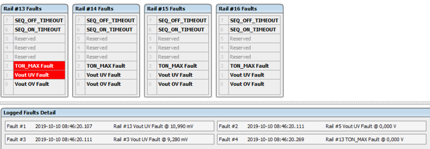
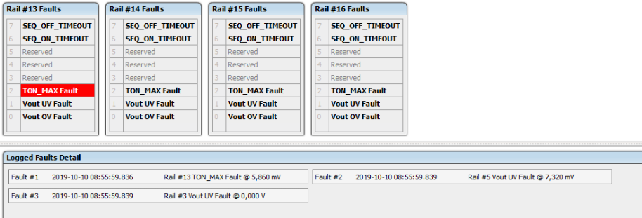
  • A resequence does not happen, if I start the board with an already disconnected couple EN-MON in which case only a TON_MAX fault occurs.

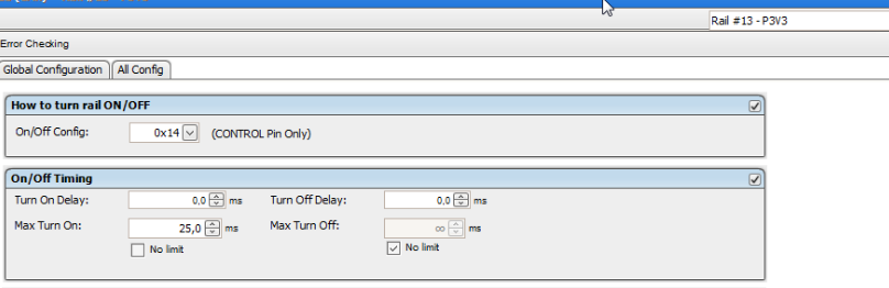
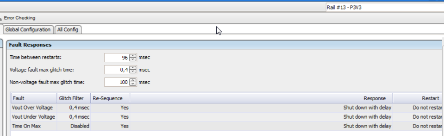
In fusion software I have programmed a fault response on both faults TON_MAX and UVF.

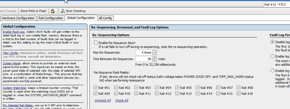
Could please help me to solve this problem : resequence on TON_MAX.

Thank you,

Best Regards,

L. B.

  • Hello

    I would suggest to set the resequencing time to unlimited instead of 4 time and also increase the sequencing interval to try? if this does not help,  please share your project file.

    Regards

    Yihe

  • Hello Yihe,

    Following your advices I was able to have some resequencing on the eval board.

    But I cannot get it to resequence on our board, which of course have different timing because it based on real supplies.

    Is there a secure way to share our project file.

    Best Regards,

    L.B.

  • Hello

     On the monitor tab or system monitor page, what's state of the rail, IDLE, SEQ_ON or others?

    you may  check the dependencies of the rails to make sure that they are good to turn on the rails.

    You can contact your local TI sale to forward project file.

    Regards

    Yihe

  • Hello Yihe,

    Thank you for your quick reply, I will try my best today to work on the subjet with your inputs, but I also requested on another matter.

    I will transmit the project file through the French AFE : P. R.

    Best regards,

    L. B.

  • Hello Yihe,

    Your advices allow me to have a first working version. I went back on evaluation board which allow me to correct some little mistakes and then I was able to have it working on my real board. I validated it today, I'm waiting now for internal feedback.

    I was requested to check GND with a monitor pin, we could read through the PMbus. The only solution I have found is to have a high power good level which disables under voltage faults. But it is generating an alert on the UCD anyway. Do you have a solution for this other point ?

    Thank you for your help,

    Best regards,

    L. B.

  • Hello

    it is great to know that you make it working.

    As for check GND with monitor pin, do you want to monitor a digital input to see whether the signal changes from HIGH to LOW.

    The best way is to use a GPI(General Purpose GPI) pin  to monitor the signal.  

    If you want to use MON pin, what you described is right but a alert is unavoidable.

    Will you consider GPI?

    Regards

    Yihe

  • Hello,

    Sorry for the delay but I was out of office.

    So far now everything is working correctly, expect the GND check with the MON input, which generates an alert and a red LED on my board.

    I know, I could have check the level with a GPI, but the requirement I have, is to check a known good voltage with a MON pin to verify that the UCD is working correctly.

    So a proposal was to check GND with a MON pin, but the result is an alert.

    Do you have an idea to avoid this alert problem or another way to check another voltage available on the UCD to verify the internal ADC.

    Thank you for your help,

    Best regards.

    L.B.

  • Hello

    What're the MON threshold settings for the GND?  is GND signal always 0V or it would be something other than 0V?

    Regards

    Yihe

  • Hello Yihe,

    Thank your for your reply.

    The max voltage measured as GND has a maximum of 30 mV due to noise (reported by the UCD).

    My thresholds voltage are Margin High 40 mV, Over Warn 80 mV, Over Fault 120 mV; Margin Low 0 mV, Under Warn 0 mV, Under Fault 0 mV (because they cannot be negatives)

    To avoid always record faults, I have programmed the Power Good On at 100 mV and Power Good Off at 50 mV.

    This globally disables the rail (and the fault checking) because the rail remains in RAMP_UP state. This is fine for me  because we just want to be able to measure the rail through the ADC using our GPP with the PMbus.

    The only problem is that the global POWER_GOOD is diasserted so the alarm pin is turn on : our red LED in always ON.

    I hope you I have describe everything.

    Best Regards,

    L. B.

  • Hello

    Have you tried to set the VOUT CAL MON the same as POWER_GOOD_ON threshold?

    Regards

    yihe

  • Hello Yihe,

    Sorry for the delay, I could not try directly your proposal. It didn't work straight with a 100 mV for Vout Col Mon for a 100 mV Power Good On, but it did work for

    for a value of 20 mV for Vout Col Mon. Now the Alert RED doesn't light on on startup.

    I still have a trouble, which can probably be solved. When I cut the power supply a 5 V one, the UCD detect it and report as a fault whereas it is the normal shut down procedure.

    Is there a way to avoid recording a Under Voltage Fault when a certain voltage drops and sequence a normal shutdown of all other rails.

    Thank you for your help,

    Best Regards,

    L.B.

  • Hello

     100mv is just a example. you need adjust based own application.

    Yes, you can disable the fault logging, please see below.

    Please be noted disable the fault logging only prevent store the fault details into the NVM. device will still shown a UV fault on the rails but without other details.

    https://training.ti.com/fusion-power-designer-enable-or-disable-fault-log?context=1136655-1139495-1136590

    Regards

    Yihe