This thread has been locked.

If you have a related question, please click the "Ask a related question" button in the top right corner. The newly created question will be automatically linked to this question.

TPS62821: How to determine the maximum inductor value with DCS Control

Part Number: TPS62821

Hello,

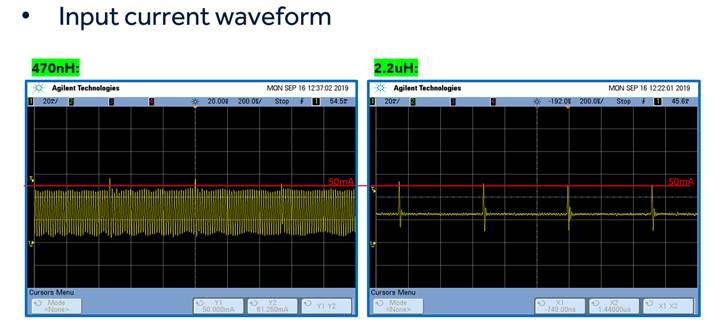
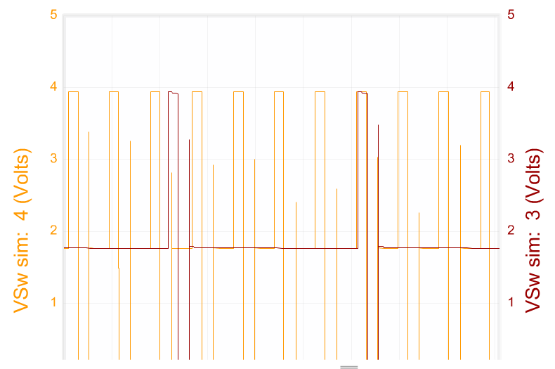
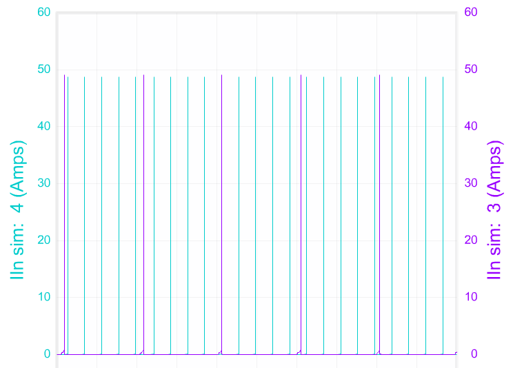
I have a customer that is using the TPS68281 device and they would like to use a larger inductor than specified in the datasheet: a value between 1-3µH. They have 5V in, 3.3V out at 10-50mA. 

The datasheet "Inductor Selection" section goes through how to calculate the minimum inductor current but I cannot find anyway to determine if a specific inductor value is too high. I know that with higher inductor values the inductor ripple current will decrease and the load current at which the device switches into power save mode will lower. I looked through a couple white papers like the following on DCS control and couldn't find an answer to this question in the papers either.

Thanks in advance!

John

  • Hi John,

    We recommend using our recommend value for design. Higher inductor will influence not only the transition point of power save mode,  but also the loop of the system. Customers need to do their own assessment of the impact, if they want to use higher inductor. By the way, why they want to use higher inductor value ?

    Best Regards,

    Kevin

    If this answers your question, Please click "This resolved my issue" button.
    ____________________________________________
    TPS62810-Q1 – New Automotive 6Vin, 2.25MHz buck family with 1% accuracy and SYNC-pin. 1-2-3-4A options.
    Smallest 2x3QFN package with wettable-flanks for optical PCB inspection.

  • Hey Kevin,

    Thanks for the response. The customer said they were trying to reduce the input current noise. They shared the following two waveforms:


    Vin= 5V, Vout= 3.3V, Iout= 10-50mA

    Thanks,

    John

  • Hi John,

    Is the time scale of these two pictures the same, could you please provide more detail information and the schematic?In principle, different inductor will lead to different working conditions under the same light load. you can see the below result: sim4  2.2uH 0.05A, sim3 2.2uH 0.05A. You can use Webench to simulate it.

    Best Regards,

    Kevin

    If this answers your question, Please click "This resolved my issue" button.
    ____________________________________________
    TPS62810-Q1 – New Automotive 6Vin, 2.25MHz buck family with 1% accuracy and SYNC-pin. 1-2-3-4A options.
    Smallest 2x3QFN package with wettable-flanks for optical PCB inspection.

  • Hi John,

    Since I have not received your reply for several days, I will turn off this item. If you have further question, you can reply it again.

    Best Regards,

    Kevin

    If this answers your question, Please click "This resolved my issue" button.
    ____________________________________________
    TPS62810-Q1 – New Automotive 6Vin, 2.25MHz buck family with 1% accuracy and SYNC-pin. 1-2-3-4A options.
    Smallest 2x3QFN package with wettable-flanks for optical PCB inspection.