This thread has been locked.

If you have a related question, please click the "Ask a related question" button in the top right corner. The newly created question will be automatically linked to this question.

TPS2115A: microcontroller GPIO loading D0

Part Number: TPS2115A

Hello,

I'm designing a circuit that utilizes the TPS2115A to auto-select one of two battery locations during boot-up. D0 is connected to a GPIO pin on a microcontroller. The microcontroller (nrf52832) pin is configured as high-impedance input (no pull-up or pull-down) until the system firmware takes over control of the power switching. D1 is connected to ground through a 220k resistor, and also connected to a pin on the microcontroller.

For some reason D0 appears to be pulling to ground when the pin is connected to the GPIO. IN1 will not be sent to the OUT pin, only IN2 seems to activate. After IN2 is inserted, the device seems to operate normalled, switching between both supplies.

This setup worked on an AVR microcontroller used for prototyping. Could this be in issue with the impedance of the nRF pin? All documentation indicates that the input leakage current is rather low, so I imagine it wouldn't be a sufficient path for the 1uA of D0. I've tried using an additional pull-up from D0 to OUT, and it does not behave differently. Any ideas here?

Thank you,

-Ryan

  • Hi Ryan,

    What exactly is your operating mode in this case? What is the autoselection basing it's conditionals on? Are you choosing input based on which has the higher input voltage?

    Secondly, what is the difference between the D1 and D0 input pins on the MCU? Why does D1 require a pulldown and D0 doesn't?

  • Hi Shreyas,

    Thanks for the reply.

    The device has two locations for a user to install a battery pack, one main, one backup. Device will include one battery pack with the option of adding a second. The autoselection will only be required during boot-up, in which case we expect one of two conditions:

    1. User has inserted battery pack in one of two possible slots, the other is empty
    2. The device is booting with two battery packs present, we want to select the one of greater voltage

    According to the truth table in the TPS2115A datasheet, autoselect mode has D1 pulled low and D0 pulled high. Since both logic inputs have 1uA pullups, we included a pull-down resistor for D1. D0 needs to be pulled high, so we allow it to do so using the internal pullup.

    -Ryan

  • Hi Ryan,

    I'm not certain why the MCU is pulling down D0. Since you are using this device in the autoswitching mode, D0 can be pulled up continually and D1 can be grounded. You say that pulling up D0 externally has no effect? Do you have any scope shots that describe this?

    Is it also not possible to leave D0 disconnected?

  • Hey Ryan,

    I would like to follow up on this thread. Have you managed to work around your issue?

  • Hi Shreyas,

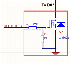
    I modified the circuit to include a MOSFET buffer as shown below:

    This seems to eliminate whatever loading issue is occuring here.

    -Ryan C.

  • Hi Ryan,

    I am glad you were able to work around your issue! 

    Thank you for choosing TI Power Switches for your designs.