This thread has been locked.

If you have a related question, please click the "Ask a related question" button in the top right corner. The newly created question will be automatically linked to this question.

TPS40210: If OC is triggered, how is the operaton of gate driving signal?

Part Number: TPS40210

Hi Youhao,

Another question is about OC protection. If OC is triggered, does the gate signal directly stop to output? and try to drive MOSFET after the restart time?

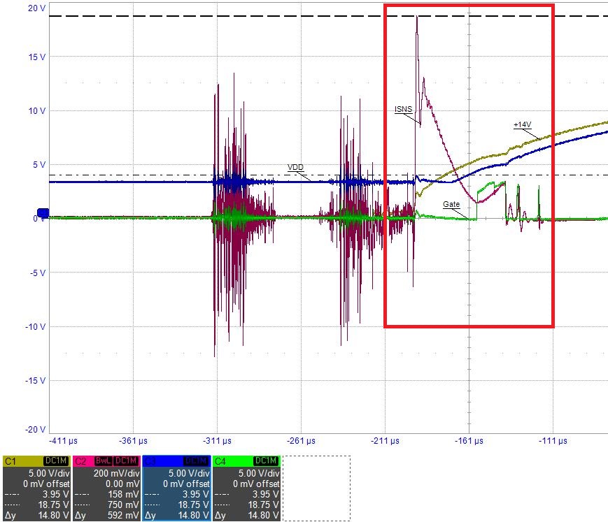
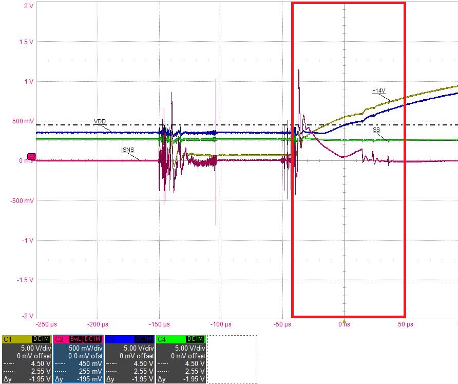
I measured PIN ISNS over 150mV, but IC still gives a few times gate signal. Is it correct operation and why?

Thanks.

  • Jammy,

    Thanks for reaching out with your questions and using the TPS40210.

    Once the OCP is trigger the gate driver will stop switching. Please note that the nominal value of the peak current limit is 150mV but can be as high as 180mV per the datasheet.

    Please let me know if you have any questions.

    Thanks,

    Garrett

  • Hi Garrett,

    Nice to meet you.

    Actually, I measured PIN ISNS voltage over 700mV to check OC is triggered.

    But the gate driver also gives signals as below waveform. Why does it do after OC is triggered?

    Thanks.

  • Hello Jammy,

    It looks like there is quite a bit on noise on the signals that you are measuring. Please make sure that you are using a tight ground loop to measure the current sense signal. Can you please take the same waveform but replace the +14V with the SS pin voltage?

    The initial spike on the sense current looks like this is coupled noise, possibly from the inrush current. The gate drive signal pulses after the current limit threshold is reach might also be due to noise coupling. If possible please post the schematic and layout.

    Please let me know if you have any questions.

    Thanks,

    Garrett

  • Hi Garrett,

    As below waveform, I think where I don't mark there is really noise on signal because of test condition.

    That is I quickly switch the switch off and then on to control the power supply of PIN VDD.

    OC is triggered at where I mark. Is that right?

    Thanks.


  • Hi Garrett,

    Excuse me. I have an additional remark.

    The power supply of PIN VDD is supplied by tow power sources. One is the input source +14V, another is one of multi outputs, +12V.

    And I control the input source.

    Thanks.

  • Jammy,

    Can you please post your schematic?

    Thanks,

    Garrett