This thread has been locked.

If you have a related question, please click the "Ask a related question" button in the top right corner. The newly created question will be automatically linked to this question.

Abnormal operation mode at no load and light load of UCC28780

Other Parts Discussed in Thread: UCC28780, ISO7710, UCC28780EVM-002

Dear Engineer, 

When I use UCC 28780 design a 65W Active Clamp Converter by referring your reference design such as TIDA-01622A;

I met with some problems. The primary inductance value is 146 uH, Rbur1=196 kOhm, Rbur2=56 kOhm, Nps=6.5; Npa=6.5; Rvs1= 43 kOhm, Rvs2=9.1 kOhm; Rcs =0.17 Ohm;

Rrdm= 95.3 kOhm, Rtz = 300 kOhm, RFB= 22.1 kOhm, Rcomp=540 kOhm, Ccomp =100 pF, Ropp = 1 kOhm.  ISO 7710 is used as high-side level-shift.

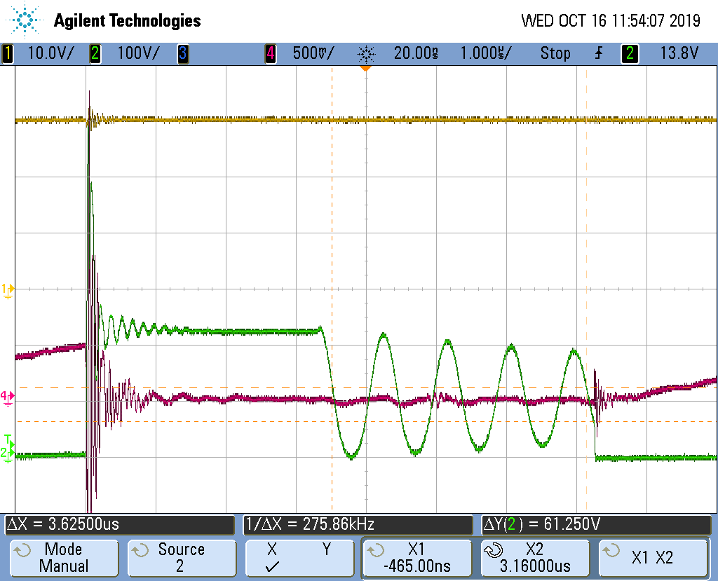
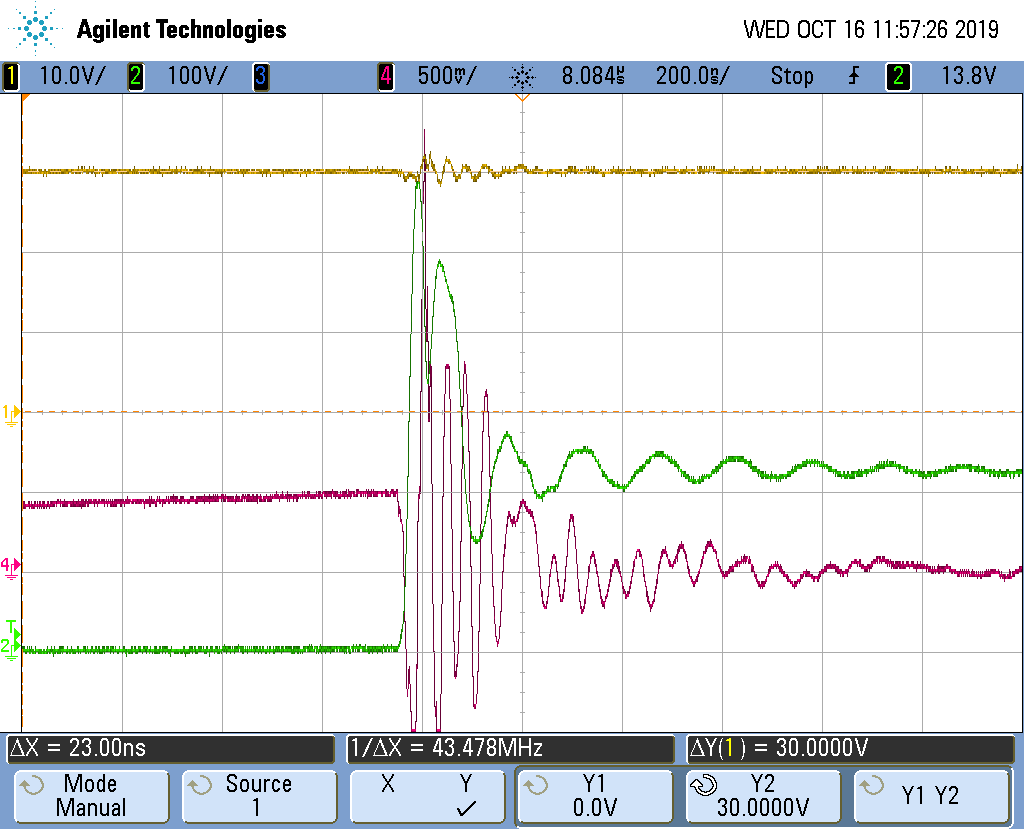
The start-up process is normal and at 80Vac the circuit could start up normally. But even at the no-load condition, the circuit would enter the AAM mode automatically, with the load current increases, the AAM keeps all the time. Taking the 90Vac input for example, when the load current increases from 0A to 2.4A, the voltage between Rcs is as following. It indicates the negative peak magnetizing current is fixed and the positive peak magnetizing current increases with the load increasing.

I would like to consult how the UCC 28780 could detect the output condition and determine the different operation modes to sustain the stable output voltage such as 20V.

The FB pin, BUR pin, and CS pin all affect the operation mode. But do they affect the operation mode together or individually? 

If the circuit enter the AAM mode with complimentary PWML and PWMH signals, what might be the reason to trigger this abnormal operation?

Thanks,

Kailun

  • It looks the UCC28780 tuner stuck inside AAM. This happens when RTZ not in a proper range so the tuner runs out of its adjustment range. Can you try to reduce Rtz to say 250k or so to see if the issue can be resolved?

    Besides, you may increase R25 to somewhere 400-ohm.

    Also, the digital isolator part number should be ISO7710F, instead of ISO7710.

  • Dear Hong,


    Sincerely thanks for your in-time reply!


    I would take your advice on the following debugging process. My test board is burnt out during the debugging process with 2.2A load current. I actually used the ISO 7710F, and thus there is no problem in the selection of digital isolators.


    In the test board with 146 uH inductance, the leakage inductance is around 7 uH, tested by LCR at 100 kHz with shorted output.


    (Yellow line_Vdd of UCC 28780; Green line_Vsw; Red line_Voltage between Rcs)


    Unfortunately, the test board is broken in the following debugging process when the load-current is up to 2.4A. Both the low-side switch and UCC 28780 are burnt out. From the test waveform, I found that the VDD was up to 30V at the load current of 2.4A. It seems that the Vdd would be charged up to a higher level in the LPM. In my case, the rising Vdd directly damaged the UCC 28780. The low-side switch is burnt out and I guess it is due to the short-circuit condition or the over-current stress. 


    In the beginning, the circuit is always operating at AAM mode, but suddenly, at 2.4A load condition, the circuit turns to the DCM mode, with large voltage spikes at the Vsw. The corresponding waveform is in the attached files, with 30V of VDD and large voltage spikes at Vsw.

    In addition, the R25 you have indicated is in the output loop. Could you tell me the reasons that the increase of R25 could make a difference?


    Furthermore, I have some questions about the Transition-mode control of UCC 28780. Usually, in the SBP and LPM, the PWMH is disabled and the low-side switch behaves like the valley-switching flyback, the low-side switch is turned on after 20ns delay with ZCD of VS pin (from 4.0V to -0.1V). However, I found that sometimes the Fsw would have a minimum limitation such as 125kHz. After low-side switch is turned off, if the tsw is smaller than 8us, even though the VSW across the Vbulk, the QL would not be turned on. But it has not been indicated in the datasheet.

    In addition, in AAM mode, when the low-side QL be turned on based on ZCD or Vth(sws)? What is the relationship between these two criteria to turn on the low-side switch?

    Finally, I found that it is really hard to design the 65W ACF with smaller primary inductance value (around 100 uH -160uH) due to the larger peak primary current. The low-side switch has been burnt out for several times. Could you give some valuable advice to implement this 65W ACF with primary inductance of 120 uH?

    Thanks a lot,

    Kailun

  • The reference designator R25 actually should be R35 in TIDA-01622, not from your schematics as I do not have your schematics. Can you please forward your schematics to me for a review?

    Can you change your inductance to be about 125uH and measured at about 300kHz? Also make the leakage inductance about less than 3 uH? These can help your debugging a bit easier from our support, as we know more with such transformer inductances.

    Can you please forward your transformer specs and real measurement including turns ratios etc?

    Can you please provide BoM if not all components are properly listed on your schematics?

    Have you evaluated our 45W EVM, UCC28780EVM-002? Can you get such a board for your reference?

    I will review these after you send them to me so I can provide my suggestions. 

  • As no further communication, I will close this thread. You can open a new thread if you have additional questions.