This thread has been locked.

If you have a related question, please click the "Ask a related question" button in the top right corner. The newly created question will be automatically linked to this question.

TPS61022: Asking for the recommendation on design - Switcher continuously fails.

Part Number: TPS61022

Hi Team,

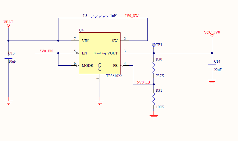
We have designed power supply with TPS61022 with the following spec
Vin Max = 4.3V
Vin Min = 2.3V
Vout = 5.0V
Iout Max = 2A

While testing the circuit we observed the following

1. While Vin = 2.4 and Iout = 1.6, the circuit produces a humming sound.
2. After this humming sound occurs, if we reduce the input voltage or increase the output current the switcher is getting damaged.

Can you please check and share with us the possible reasons for the failiure or suggest to us a switcher that is able to produce the above spec without fail?

  • Hi Hari,

    Could you share the schematic and layout?

    Have you capture SW, Vout pin waveform with digital oscilloscope?

  • Hi Zack

    I am attaching the sections of Schematics and Layout containing the power supply circuit. Please find the attachments.

    Also, I didn't capture SW and Vout pin waveform with digital oscilloscope.  W, Vout 

  • Hi Hari,

    For 5Vout/2A applications, TI recommends using effective output capacitance bigger than 20uF. So please use 2*22uF output capacitor in parallel or use a higher value ceramic output capacitor for C14.

    The schematic doesn't show me the inductor part number. What's the saturation current spec of the inductor L3? You may need to use a Isat higher than 8A inductor.

  • Hi Zack ,

    I have tested with the recommended capacitance added and with an inductor with the high current rating (Part No: VLP8040T-2R2N , Mfg: TDK)  and still have the issues.

  • Hi Hari,

    What's the capacitor C14 part number (or value) are you using? Do you have VLP8040T-1R0N (1uH) on hand and try it again? The reason is 2.2uH inductor will let the right half plane zero lower in this condition, causing a lower phase margin and gain margin.

    Does the damage issue happen on several board or only this one? Can you use digital oscilloscope to capture SW, Vout pin waveform?

  • Hi Zack,

    C14 part no is C2012X5R1A226M085AC.

    We don't have  "VLP8040T-1R0N " in stock.

    The damage happened in few ICs, I have only 2 remaining in stock. So since it is continuously damaging I am not confident in doing the testing again until we figure out a possible reason for the failures. If those 2 fails we might need to wait for another week to get the IC.

    Also I didnt understand the following statement "The reason is 2.2uH inductor will let the right half-plane zero lower in this condition, causing a lower phase margin and gain margin." 

  • Hi Hari,

    When choosing capacitor, it's important to take care of capacitance derating under voltage bias. I checked the datasheet of C2012X5R1A226M085AC and find at 5V DC bias, the effective capacitance is only 5.226uF. 

    In Boost converter topology, inductor will introduce a right half plane zero in the transfer function. If this RHP zero frequency is close to cross over frequency, the phase margin will not be enough.

    I also found the instability behaviors in simulation if output capacitance is 5.226uF and inductor is 2.2uH, may causing device burns out. So in summary, choose a 1.0uH inductor with current rating higher than 8A and effective output capacitance higher than 20uF, such as 4*C2012X5R1A226M085AC


  • Hi Zack, 

    I have probed VIN, SW and VOUT under the following conditions.1. Vin =3.3V , Iout = 2A
    2. Vin =2.9V , Iout = 1.8A
    Then I increased the Iout to 2A  when  Vin =2.9V and the switcher get damaged.
    I am attaching the observed waveforms under the above-mentioned conditions.
    Since all the switchers in stock were damaged I have ordered few switchers and the Inductor that you mentioned in the previous post (1.0uH inductor with a current rating higher than 8A).
    I shall let you know the results after checking with them once it is received.
  • Hi Hari,

    I try to replicate the unit failure on EVM. I also found instability behavior with inductor 2.2uH and Cout C2012X5R1A226M085AC when input voltage is 2.4V and Iout=1.4A. SW, Vout pins voltage may rings high to 7.5-8V, higher than the absolute maximum voltage rating 7V.

    So select a 1uH inductor and use 4*C2012X5R1A226M085AC as output capacitance. Hope that help you.