This thread has been locked.

If you have a related question, please click the "Ask a related question" button in the top right corner. The newly created question will be automatically linked to this question.

UCC2897A: Main switch MOS tube Vds waveform question.

Part Number: UCC2897A

Hi,TI

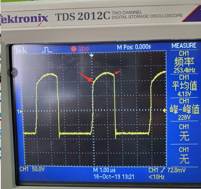
       When UCC2897A is used as the active clamping forward power supply, it is found that the Vds waveform of MOS tube is like this. As shown by the red arrow, the charging point of clamping capacitor is inconsistent with the discharging charge. What is the reason?
  • Hi Tracy,

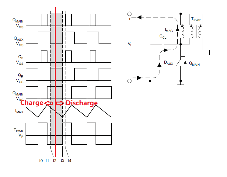
    During the main MOSFET turn off interval, the voltage on the FET equal to Vin + Vcl for a high side clamping configuration. where , Vin is input voltage and Vcr stands for the voltage on clamp capacitor. ignore the dead time between two FETs ,  Clamp capacitor is resonant with magnetizing inductance during clamping FET on time . See below image , before the demagnetizing current(Imag) decrease to zero . the current on primary side was charge the clamp capacitor , indicated by a rising voltage on clamp capacitor. once demagnetizing current below zero . the clamp capacitor was discharged . you can find a decreasing voltage on clamp capacitor , as well as on Vds of Main FET. So that is normal behavior.

    Hope can answer your question. Thanks.

  • Hi,Jaden

    My understanding is that the clamping capacitor charge and discharge corresponding to the waveform is not supposed to be used in a horizontal line?
    In addition, when the output current increases, the amplitude of Vds will jitter, the larger the current, the more jitter.May I ask what causes this?

  • Hi Tracy,

    The Non-horizontal line point of VDS at main FET turn on and turn off point was caused by leak inductance and PCB trace parasitic inductance.

    when Main FET turn off , the peak primary current on above leakage inductor will lead to a opposite voltage on VDS of main FET , but at turn on point.

    there is a ZVS turn on with very little negative current.

    I didn't see the waveform you mentioned the jitter on VDS when output current increase, but I guess whether you have lost the ZVS , the hard switching of Main FET will cause a spike on Vds .

    Thanks.

  • Hi Jaden

    I think it is likely that ZVS is not implemented. MOS tube is also hot under the condition of light load.I would like to know how to test to confirm the implementation of ZVS? Thanks.

  • Hi Tracy,

    You can capture the Vgs and Vds of main FET and the current of transformer primary winding in the same waveform.

    If there is a negative current and Vds already resonant to zero before the Vgs go high, that is means ZVS implemented.

    Thanks.

  • Hi, Jaden

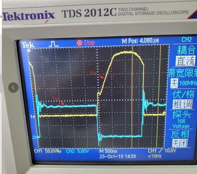
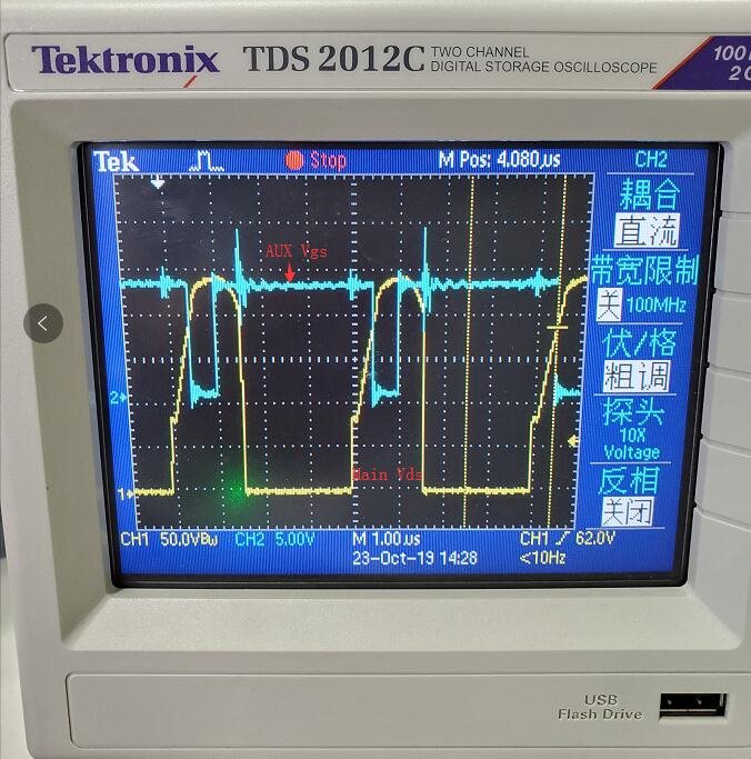
    Please look at my waveform and see if ZVS has been implemented. And I feel the rising edge of the main switch Vds is a little strange, do not know what is the reason, according to the principle should be vertical up.

  • Hi Tracy,

    Our resource for E2E support is limited , we have asked much questions in this post.

    I think you can find many papers and documents in the internet to find out answer for your questions.

    If you have further questions about the controller UCC2879A, could you please create a new post and close the post ?

    Thanks.