A related question is a question created from another question. When the related question is created, it will be automatically linked to the original question.
If you have a related question, please click the "Ask a related question" button in the top right corner. The newly created question will be automatically linked to this question.
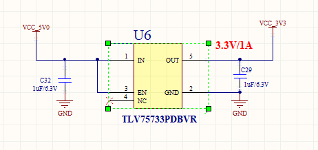
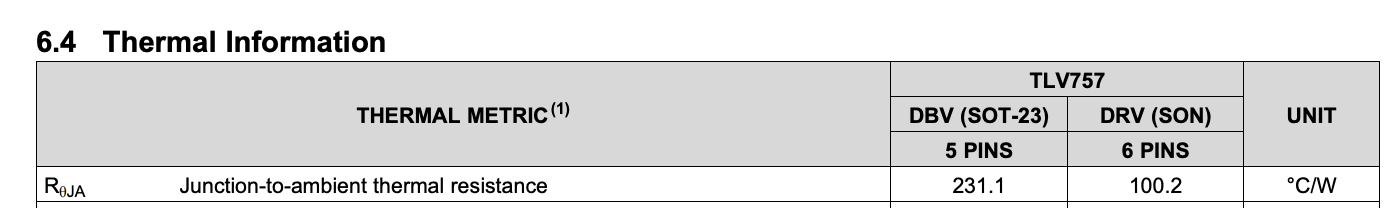
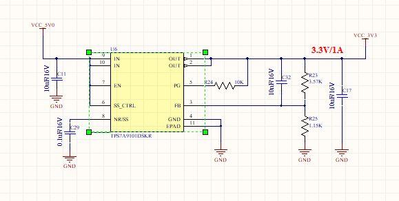
The schematic looks fine. If you do plan to have a nominal 1A load current, Pay attention to the thermals:
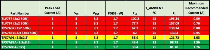
The SOT-23 package has a TJA of 231.1C/W. So with (VIN-VOUT)*ILOAD= 1.7W, the junction temperature would rise to 392.87C. So the device would be constantly shutting down thermally. With 5VIN and 3.3VOUT, your nominal load current should be less than 250mA. Changing to the DRV package would increase the load current capability significantly before running into thermal shutdown, but even this package can not dissipate the heat with 5VIN and 3.3VOUT.
If you compare to a device like our TLV767 or TPS7A91, those have much better thermals with the TPS7A91 being closer to being able to support your 1A load.
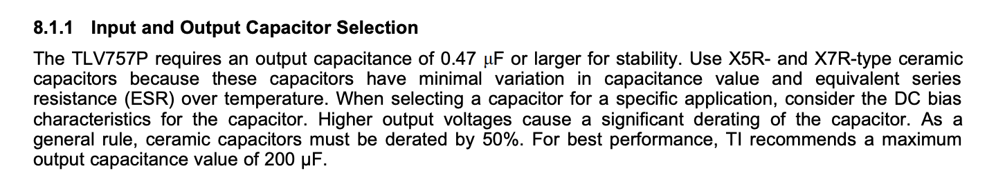
Also please make sure your output capacitor is either an X5R or X7R dielectric as we need a capacitance of 0.47uF to guarantee stability:
1.C32 is referred to as a Feed-Forward capacitor. This helps to improve PSRR (Power Supply Rejection Ratio) below ~100Khz. It is optional if your load does not require super high PSRR
2. If you don't want to use the PG (Power Good) pin, you can either float or ground the pin as this is an open-drain output. There is nothing wrong with pulling it up to VCC with R24.
3. You have pin 5 (SS_CTRL) tied high with a 0.1uF cap on NR/SS (Noise Reduction/Soft Start). If you don't want a soft-start function, you can ground SS_CTRL and remove C29. Again there is nothing wrong with the circuit as is, I am just assuming you don't need this functionality as it was not in the previous device.
1.C32 is referred to as a Feed-Forward capacitor. This helps to improve PSRR (Power Supply Rejection Ratio) below ~100Khz. It is optional if your load does not require super high PSR
Manjunath : Thanks Noted.
2. If you don't want to use the PG (Power Good) pin, you can either float or ground the pin as this is an open-drain output. There is nothing wrong with pulling it up to VCC with R24.
Manjunath : Thanks Noted.
3. You have pin 5 (SS_CTRL) tied high with a 0.1uF cap on NR/SS (Noise Reduction/Soft Start). If you don't want a soft-start function, you can ground SS_CTRL and remove C29. Again there is nothing wrong with the circuit as is, I am just assuming you don't need this functionality as it was not in the previous device.
Manjunath : Understood, wSS_CTRL is connected to ground and For NR/SS pin, If remove the capacitor, this pin will be floating right? WIll keep this pin floating? or GND?