This thread has been locked.

If you have a related question, please click the "Ask a related question" button in the top right corner. The newly created question will be automatically linked to this question.

TPS92641: TPS92641 unstable at 2A output current

Part Number: TPS92641

Hi,

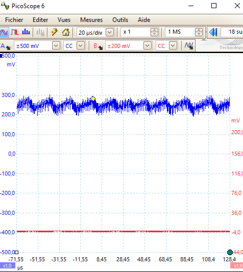
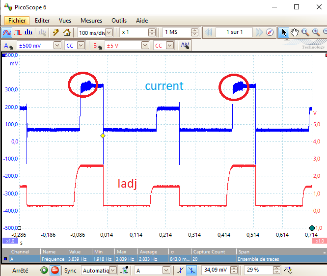
Seems that the current output at 2.2A is unstable in my application. (noise between 3 and 10 KHz)

We play with the ADJ pin to programm either 1.2 or 2.2A.

Everthing else same as reference schematic.  (COMP cap = 470nF, inductance =  68µF, 3A,  output cap = 2.2µF,  power led =  15V@2A,  input voltage stable at 24V)

Any idea to get a good waveform ?

Michel

  • Hello Michel,

    Is this your own board layout or a modified EVM?  Do you have a schematic with all of the values/components that you are using?  Several values must be different from the EVM such as the values for current sense and UVLO.

    Can you get oscilloscope pictures of the circled area zoomed in?  Also other signals such as the drain waveform during this period, inductor current if that is possible. 

    What is the inductor you are using?  MOSFETs?

    Best Regards,

  • Hello Michel,

    I haven’t heard back from you, I’m assuming you were able to resolve your issue.
    If not, just post a reply below (or create a new thread if the thread has locked due to time-out)

    Best Regards,

  • Dear Irwin,

    Actually, the issue is not solved. Attached is our schematic. (not sure if attachement works)

    Inductor is Wurth : 7447709680

    Mosfets are: DMN3018SSS-13

    current sense resistor is 0.1 Ohm.

    Layout is also different as the TI board.

    Looks that the current has some instability at 50KHz.

    Br

    Michel

    power_leds_schematic.pdfpower_leds_schematic.pdf

  • Hello Michel,

    I have a few more things to ask.  What does the ground look like between the current sense resistors and the IC ground?  Is is a plane, trace, how far away?

    Can you look at the input voltage when this happens?  Also can you show Vled with the current pulses?  Are you commanding Iadj to zero when it is low?  There appears to be a long delay from when Iadj rises to when the output current rises.  Can you also look at COMP when your are pulsing the current.

    Best Regards,

  • Hello Irwin,

    Attached is the layout of the 4 layers.

    Input voltage (24V) is stable.

    Vled has noise at the same frequency as the current measure.

    Yes, we switch adj to 0 (not shown on the schematic, additional wire)

    I will look at Vcomp tomorrow.

    I noticed one difference with the reference design: there are no resistors in series with the gates of the switching mosfets. Difficult to test at this stage.

    Note that we drive two leds (not at the same time). One is stable and the other not !

    Thanks for your help.

    Michel

    3666.Layout.zip

  • Hello Michel,

    I don't really see anything with the current sense path and ground seems solid.  Probably didn't need a CS plane on layer four since there is no current in that path but layer three is ground so it should be okay.

    I don't think resistors in the gate will make a difference for this.  The Qgate is fairly low on your parts so they will have fast rise and fall times.

    Could you describe the two leds where one is stable and one is not?  Are there wires to the LEDS and if so is there capacitance at the LEDs (across the LED load)?

    Are Q3 and Q4 used for switching the LEDs?  Is this where one LED load works and one doesn't?  What is different about the LEDs being attached?

    Best Regards,

  • Hello Michel,

    I haven’t heard back from you, I’m assuming you were able to resolve your issue.
    If not, just post a reply below (or create a new thread if the thread has locked due to time-out)

    Best Regards,