This thread has been locked.

If you have a related question, please click the "Ask a related question" button in the top right corner. The newly created question will be automatically linked to this question.

TPS23754: priority confirm

Part Number: TPS23754

Hi Team:

RD would like to confirm DC_IN & POE priority on DEN_DC_POE pin and test step as below

1.When DC_IN disable , it's 48V

2.Disable POE than connect DC_IN 12V , it's 0.96V

3.when enable DC_IN and POE on the same time , it's 48V  and POE still provide power 

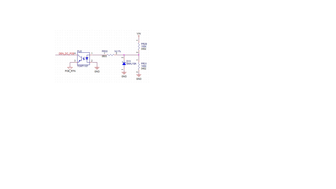
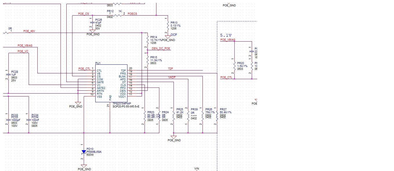
How could we confirm DEN_DC_POE pin to know priority ? and schematic as attached , please help to confirm schematic,  it's correct or not , thanks.

Regards / Mark
  • Hello,

    Thank you for your question. 

    Priority between an adapter input voltage and PoE is thoroughly explained in the following application note: http://www.ti.com/lit/an/slva306a/slva306a.pdf

    This application note explains the different ways to do priority, and how to setup the circuits. I think this will be a good resource for you for this topic. It looks like you are doing priority option 3. Please correct me if I am wrong.  

    I am assuming that "it's" in steps 1, 2, and 3 are PoE VDD input. Please correct me if this assumption is incorrect. 

    In this setup, when VIN goes high to enable the optocoupler, then the PoE is turned off. This is accomplished because the detection resistor is no longer valid, and MPS current is too low. Therefore, the PSE will turn off power to the PoE PD. That is when the adapter will take over, because the Vout of the DC-DC is now lower than VADP. To confirm this, as you said, PoE input will no longer be 48V, but something else. This will shut off the IC. you can confirm this as you said, with VDD, or you can check the resistance between VSS and RTN to prove the hotswap MOSFET is turned off. 

    To confirm that PoE is priority when both are present, you need to confirm the PSE is still supplying power. That can be measured by checking either the hotswap MOSFET, checking the MPS current, checking the DC-DC converter, checking the voltage drop across DA. Something to note is the output voltage of the DC-DC converter (listed as VOUT in the app note) must be higher than VADP, and VADP must have a diode (DA in the app note). That is why you can measure the voltage across it for confirmation. 

    So the test you described is fine. 

    For the Schematic:

    D13 should be between VDD and VSS, not VDD and RTN.

    Additionally, I cannot see where V_ADP goes to, but this is what will power the output voltage when PoE is disabled, so ensure that it is connected to the output as in the app note figure 9. 

    Regards,

    Michael Pahl