This thread has been locked.

If you have a related question, please click the "Ask a related question" button in the top right corner. The newly created question will be automatically linked to this question.

TPS82130: Reverse Powering of TPS82130 and LMZ31710 Converters

Part Number: TPS82130
Other Parts Discussed in Thread: LMZ31710

Hello everybody,

we are designing a system including TPS82130 and LMZ31710 SMPS.
In the final product it is possible that the external sources inject small currents (< 50 mA) into the powered net.
Some regulators can take damage from this due to the voltage difference between input and output.
Also a charging current to the regulator input power net and its capacitors can also cause damage.
I guess the latter is unlikely due to the low current of < 50 mA.
The datasheets of TPS82130 and LMZ31710 have no clear statement concerning these situations. In datasheets for linear regulators one can sometimes find the advice to add a diode between output and input to shunt this reverse current.

So my question is:
What is the expected result of injecting max. 3.3 V and 50 mA to the output of a TPS82130 or LMZ31710 when they have no power source at their inputs?

  • Hi Johann,

       Will your system tolerate if you have a 50mA load resistor (like a leakage resistor) at the output? This can load the current being injected into the output cap and keep the voltage at the output from raising. If the injection source is a 50mA current source, then the voltage on Vout can increase and can potentially damage the caps and the IC depending on the voltage built on Vout.

    regards,

    Gerold

  • It is a signal source with Vmax = 3.3 V and Imax = 50 mA.
    I the charging of the capacitors on the net will delay the rise of the voltage.
    But after this, the maximum voltage on the Vout of the regulators will be 3.3 V.
    Can this cause damage ?
    The regulator are not powered and their Vin is open, it is not shorted.

  • If I understand correctly, you will be applying a voltage source of 3.3V that is current limited to 50mA (not forcing 50mA).

    Can you keep the TPS82130 EN low and LMZ31710 INH pin low to keep the parts disabled when you are applying this external source?

    What are the actual set output voltage points for the TPS82130 and LMZ31710 during normal operation? Are they both designed for 3.3V output nominal?

    If you can keep the devices disabled (EN and INH low) while applying the 3.3V at their outputs, and inputs open/floating, I believe there should be no concern for damage. Even if 3.3V conducts to the input through the HS body diode, the devices will not try to start switching since the parts are disabled, so you should see minimal current draw through the devices with the parts shutdown. That is assuming nothing else is tied and loading the TPS82130 or LMZ31710 inputs. Anything at their inputs will see this conducted voltage.

    If it is possible to do so on your board, I would recommend disconnecting any loads to the TPS82130 and LMZ31710 rails, and applying the 3.3V source and measuring the current draw pulled from your source through the devices.

  • By the way, here is an article you may find useful/relevant: https://e2e.ti.com/blogs_/b/powerhouse/archive/2017/01/20/can-i-apply-an-output-voltage-to-my-dc-dc-converter

    This app note may also be useful: http://www.ti.com/lit/an/slyt689/slyt689.pdf

    Can you share information on this external source and why it is applying this 3.3V signal to these buck converter outputs? Is it part of some kind of testing you are doing?

  • Thank you very much for the links.

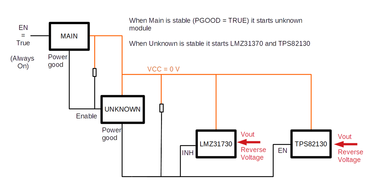
    We have a connection between two devices and one could be without power whilst the other is transmitting data.
    This would then propagate to the power supply, but I guess it causes no damage due to the low current.

    The INH/EN pins of these smps (TPS82130/LMZ31710) are only held low by the power good output of the previous powersupply stage.
    I don't have the schematic of that previous stage and there is no additional resistor to pull it down.
    The Powergood is connected via a 10k pullup to the output of the main power supply, but i might add a large resistance pull-down to improve on this without disturbing normal operation.
    Maybe this is better than my description.

  • Hi Johann, the LMZ31710 and TPS82130 may remain disabled anyway due to their UVLO. The 3.3V reverse conducting to VCC will be a diode drop lower or around 2.6-2.7V, which appears to be below the UVLO rising thresholds of these devices.

    You may want to see (experimentally) what is the minimum supply voltage that turns on the Unknown power stage since it will see the 2.6-2.7V at its supply terminal according to your diagram.