This thread has been locked.

If you have a related question, please click the "Ask a related question" button in the top right corner. The newly created question will be automatically linked to this question.

LM317: Linear circuit with loss ground

Part Number: LM317

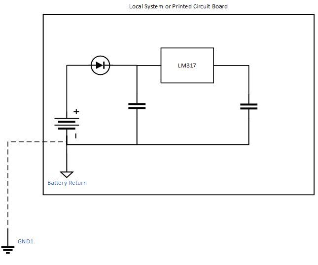
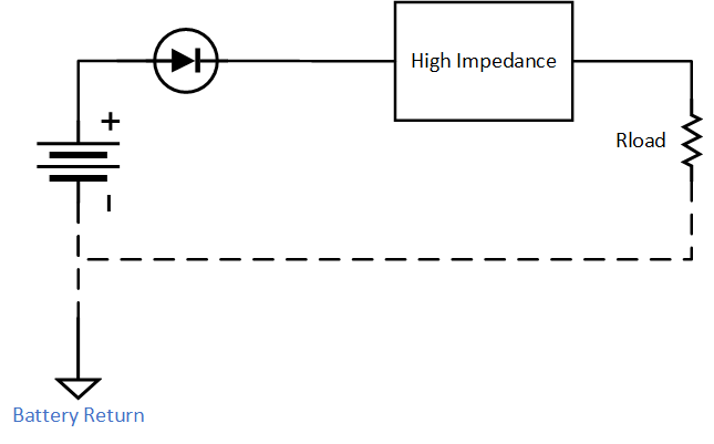
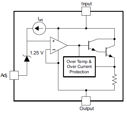
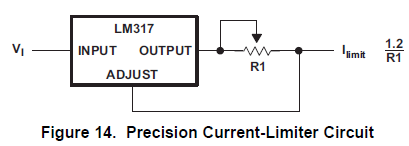
I have a product using a LM317 using a simple circuit like below:

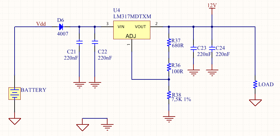
It uses a 24V battery as source (between Vdd pin of circuit and ground of circuit), and output is 12V.

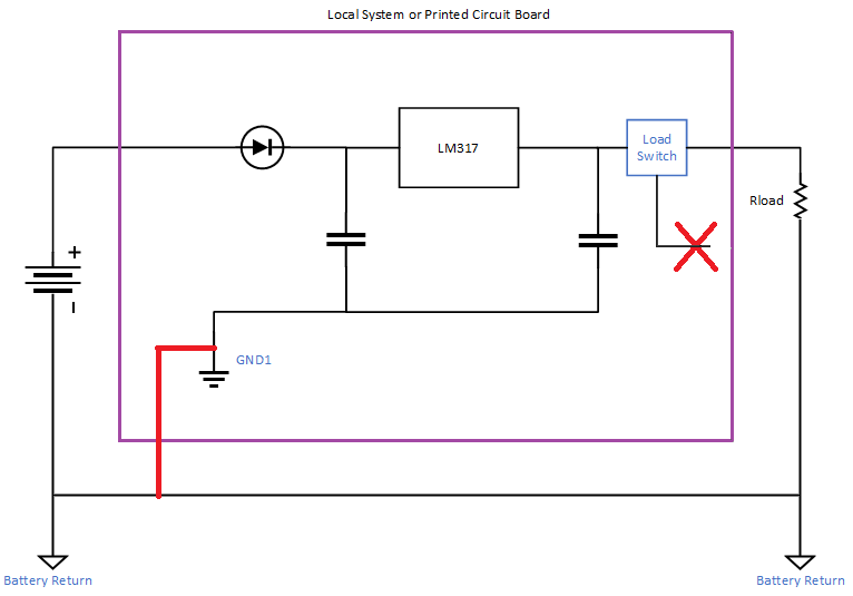
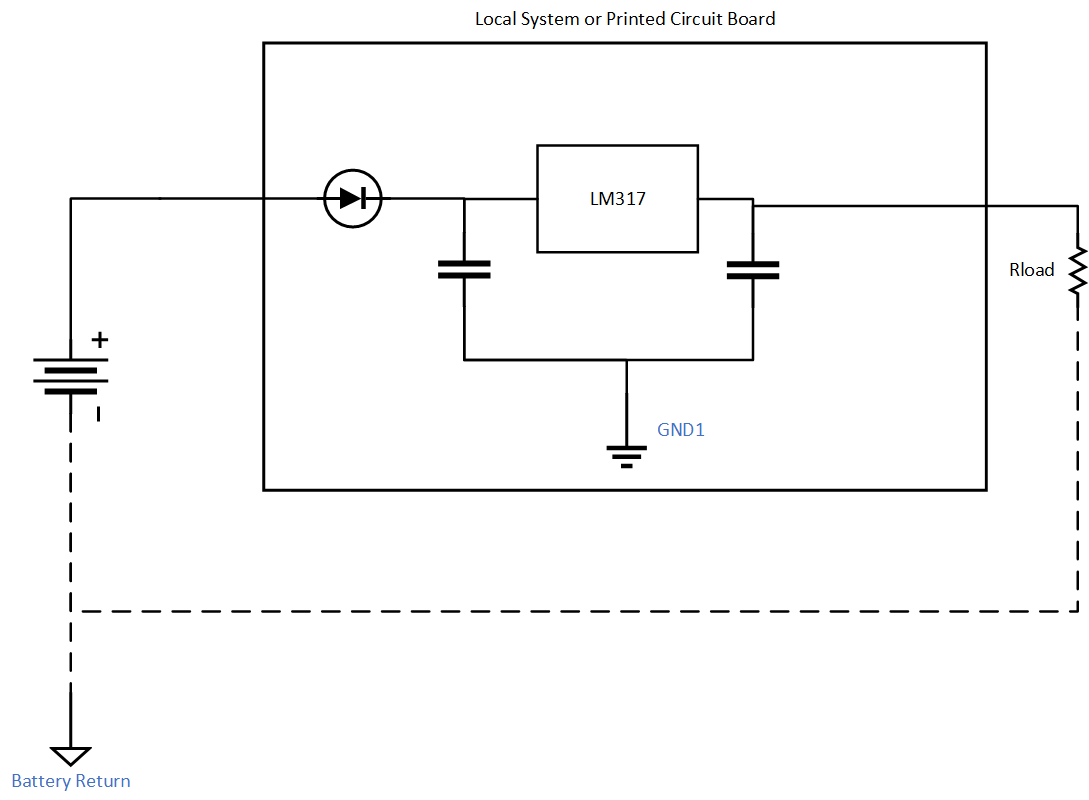
When the circuit is working at steady state and loses the connection with battery ground all battery voltage goes to the Load

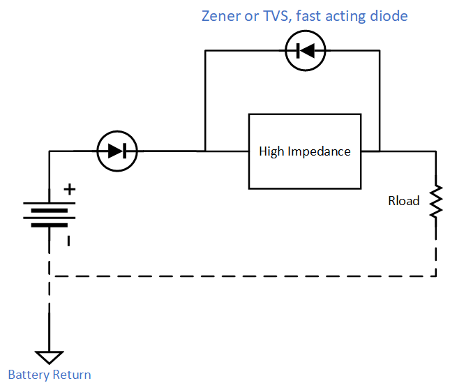
I need to protect the load under this circunstance.

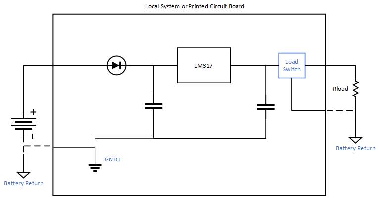
I thought about 2 option, stop LM317 from conducting or adding a switch at output (Vout pin from LM317), first option I think is not possible and second one I tried a P channel mosfet, it works but it is not fast enough to avoid 24 V at load before it cuts off the output connection.

There is anything I can do to accomplish this need without changing LM317 to another component?

  • Hello,

    I can help but I may need further details on the system, specifically how the ground and return connections are becoming disconnected.
    If this is a test called out by a specific specification, can you provide the name of the specification and which test it is?
    I've listed two options and a possible path forward, but we may need to discuss further if you can clarify these details.

    Additionally, I am curious if the battery voltage is measured across the Load resistor shown in your schematic, and whether it is also measured on the output of the LM317 with respect to the ground of R38.

    If the battery and LM317 circuitry are local to each other, then the first thing I would look at is making the return, or "ground", of the LM317 circuitry the same as the battery.  When the ground connection is lost this simply means the electronics will be floating, but they will still have a local return and will operate correctly with respect to that local return.  Many systems operate perfectly fine without a firm connection to earth ground, such as airplanes and satellites, so this is not a new idea.

    The second option is more challenging.  The idea is that the battery is located away from the electronics, and is connected through a harness.
    Some mechanism causes the harness return to disconnect from the electronics, while the "ground" connection is still present.  As you mentioned, a robust solution would be to add a load switch to the design that requires the battery return to be enabled.  You must also worry about common mode voltage on any electronics when an external battery like this is removed then reinserted.

    Again, if you can clarify the system details, we can discuss further.

    Thanks,

    - Stephen

  • Hi Stephan,

    Thanks for your prompt reply.

    The system is pretty simple, it is a bus system that needs to convert 24 V battery to 12 V to supply a low power load that can't afford a voltage higher than 15V.

    This "battery return loss" (like you described) is something frequent and we lose the connection with battery return (in red at image below) and the product must protect load against it. Basically we dont have access to Reference point of battery (Battery Return) and it still keeps connected to the load. The battery return is connected directly with the load, also positive of the battery keeps connected to the circuit, the load and battery return are connected outside of product, like image bellow. Also we cant use the product case (harness) as ground due to specification restrictions.

    The product has only 3 points of conection with outside of printed circuit board:

    1. Battery + Voltage,

    2. Load + Voltage (LM out)

    3. Battery return throught red connection on image above.

    The connection loss is in point 3 (red wire in image above) and we cant get it back on circuit physically.

    Hope I understood your questions, if something is not explained well feel free to ask more details.

    BR,

    João Paulo Mazzotti

  • Thanks for the clarification João.

    When the system loses connection to the GND of the battery, my first thought is that the LDO will turn off and the input - output nodes will become high impedance.  I measured an LM317 while it was powered off and the input-output impedance is 4 Meg ohms, as measured on 3 different HP 3478A multimeters, and 4.75 Meg ohms as measured on a Fluke 45 multimeter.  The series diode would be low impedance as it would still be conducting.  When the battery return becomes disconnected, I think you will have the following schematic:

    To the system, it will look something like this.
    Your Rload must be very high impedance as this looks like a voltage divider, and you said the battery voltage is going across Rload.

    Our only option with the floating CCA is to add a series element to protect the load.
    Ideally it will not need to be in series with the first diode and LDO, which prevents power loss during normal operation.
    I am wondering if a zener diode or something similar across the input-output of the LDO will be enough.
    Perhaps we need a TVS diode?  You may need to evaluate several diode options.

    Thanks,

    - Stephen

  • Dear Stephen,

    I have tried as you suggest with a TVS diode, but nothing changed in the circuit behavior.

    Under this circunstace the output voltage on the LM317 is the same as input voltage, this behavior isn't like a short circuit instead of a high impedance?

    If you analyze the internal diagram of LM317 like below:

    When you did analyze the LM317 as high impedance, is it completly with no energy in the circuit right? But if you have a voltage at input pin, with Adj. Pin open, internal darlington will act as a short circuit, or am I analyzing it wrong?

    Think only way I can go is with a series load switch, but not sure how to assure it will block with no reference, any idea of another option or how I can accomplish it is welcome.

    BR

    João Paulo Mazzotti

  • Hello João,

    If the RTN of the LDO is not connected to the battery return, then there cannot be any current flow and the device is turned off.  The same goes for any circuitry on the PCB at this point.  Once you remove the CCA from battery ground, there is no "circuit" that current is flowing through.  The measurement I took of the LM317 was with no power applied, but this would be correct if the RTN of the LDO is not connected to the battery.

    I view the NPN as two diodes, as described by the Ebers-Moll model.
    As you can see, the BJT is not low impedance (I.E. it is not a diode) when powered like this.
    I took the following image from Wikipedia.

    I think you will need a high speed series switch, or some series element such as a zener diode in series with the regular diode, or possible a series TVS.
    The design will be challenging once you consider tolerances.  For instance, max battery voltage will play an important factor.

    Thanks,

    - Stephen

  • Dear Stephen,

    Thanks for your reply, but I would have to insist about it. I understand about ebers-moll equivalent circuit, and understand your point. But the circuit behavior is not acting like that, that is my point.

    I know usually the simplify circuit shown in the datasheet is a very simplified one and everything inside is not shown, and now you said about high impedance and circuit behaviour doesnt match with.

    I did the following test:

    1º Assure output voltage = 0V

    2º Connect battery return to the load (not to the circuit)

    3° Connect the Load to output circuit

    4º Connect battery positive terminal

    After 4º step the output voltage is equal input voltage, if LM317 should act as a high impedance output voltage would be zero and all voltage would be at LM317, and it is not happening.

    My thought is LM is changing from Voltage regulator to Current regulator with R1 = 0R (below Image) since adjust pin is floating, may I be right?

  • Hello João,

    It could be that the load impedance is much higher than the LM317 impedance when no RTN is connected to the LM317.

    If you design a current source, then the LM317 will regulate current and not voltage.
    Is that what the application needs?

    I still think you need a series protection device with tight tolerances, given the system requirements.

    Thanks,

    - Stephen