This thread has been locked.

If you have a related question, please click the "Ask a related question" button in the top right corner. The newly created question will be automatically linked to this question.

BQ24725A: never starts charging sequence

Part Number: BQ24725A

Hello,

I implemented a BQ24725A in one of my design for a project.

We basically copied the datasheet design with the same part numbers to have minimum risks.

The problem is that the IC never starts charging our battery pack.

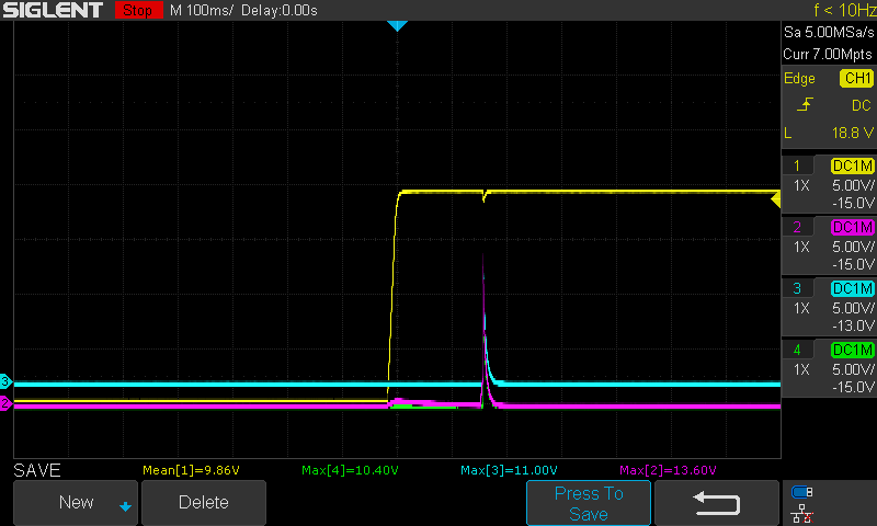
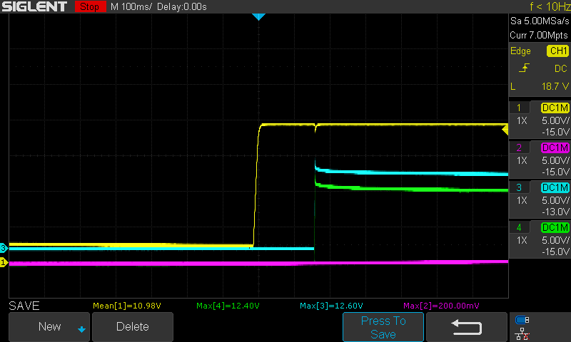
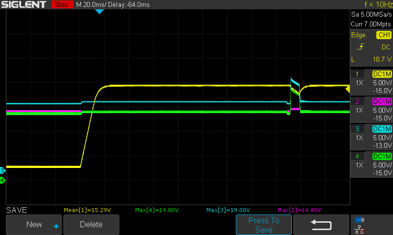
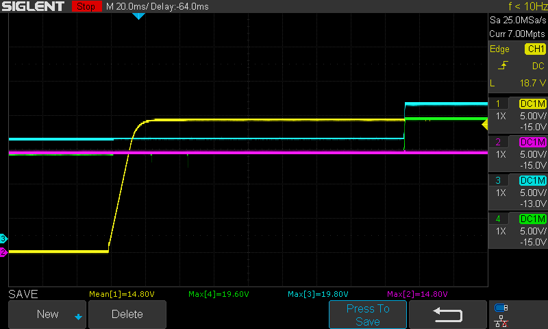
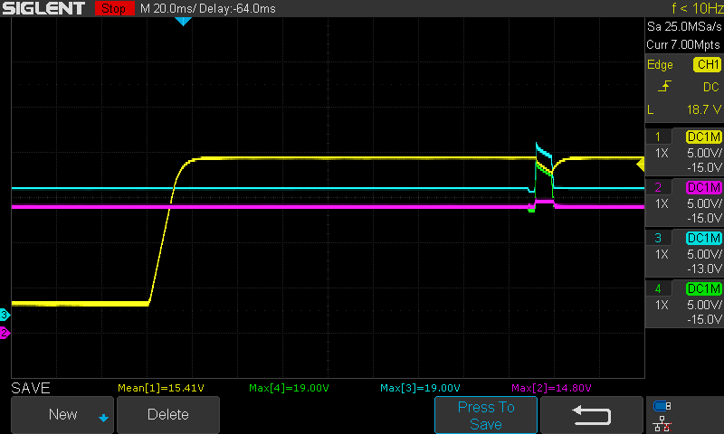
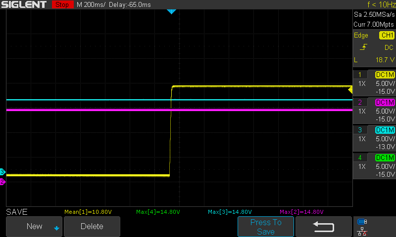
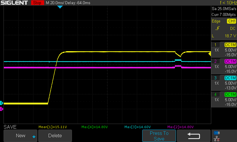
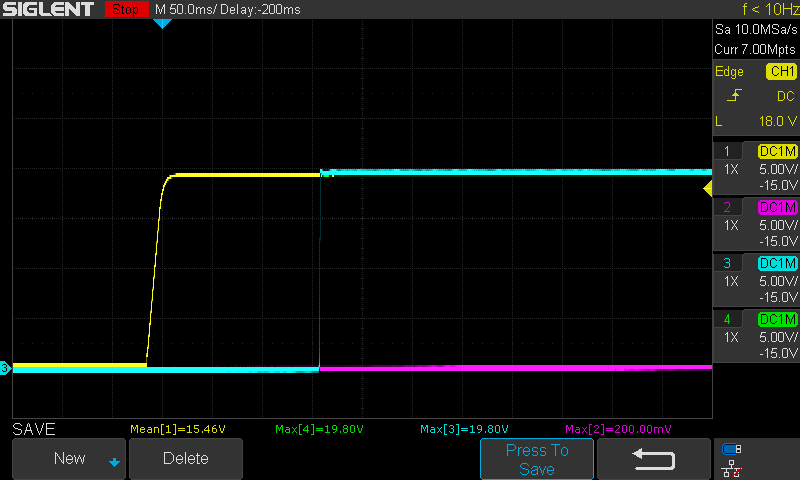
We observed that the ACFET and RBFET won't let the voltage pass when the cells are connected.

The ACFET and RBFET works properly when there is no cells connected to the circuit.

The IC detects the input voltage with ACOK.

We tried to investigate the problem with the different questions asked before but none answered our problem.

We designed for a 4S2P setup but we tested with a 4S1P setup (14,5V).

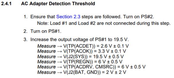
Our input voltage is 19,5V just like in the evaluation board procedure.

ILIM is 0,8 V

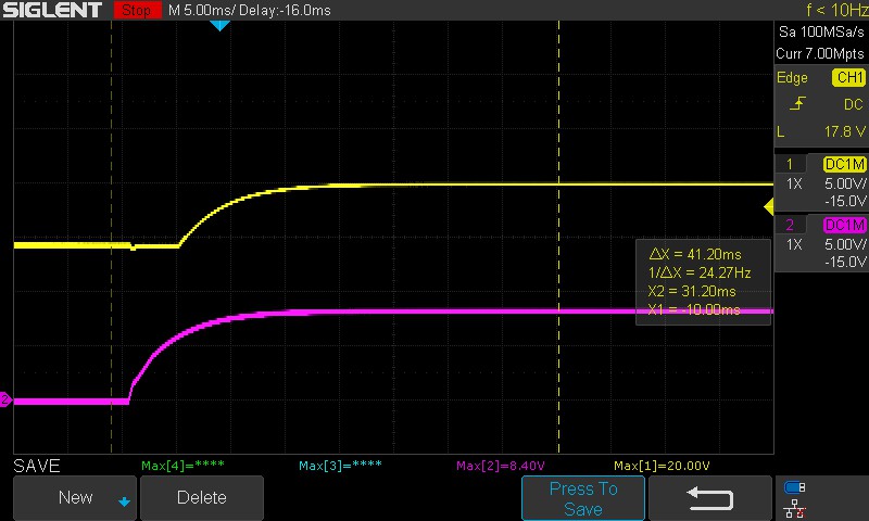
We did every step below, and every voltage had the right values.

Our registers are set to :

ADD     -     VALUE

0x12     -  0x8630

0x14     -  0x0640

0x15     -  0x41A0

0x3F     -  0x1F80

The sequence for programming the chip is :

1 - Charge option configuration with enable bit to 1

2 - Charge option configuration with enable bit to 0

3 - Adapter current configuration (0x1F80) (8A)

4 - Charge voltage configuration (0x41A0) (16,8V)

5 - Charge Current configuration (0x0640) (1.6A)

6 - Read all registers (all values are fine)

7 - Loop every second (step 2 to 7)

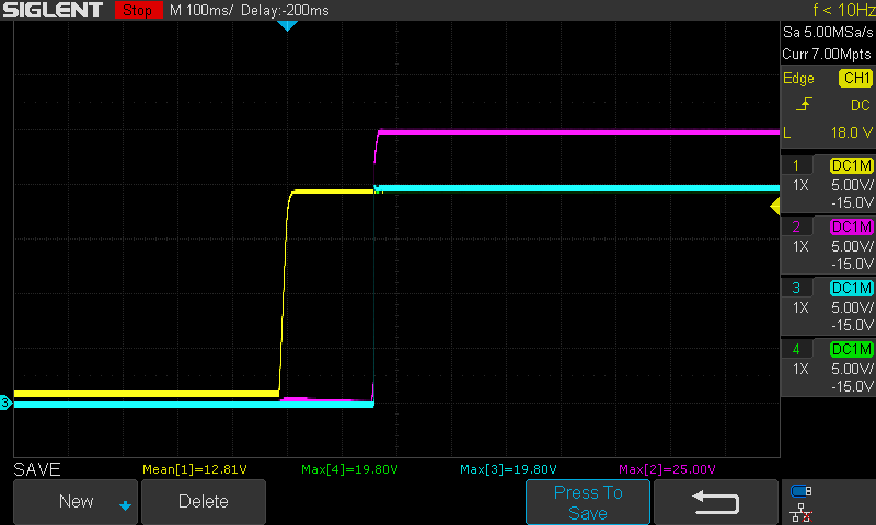
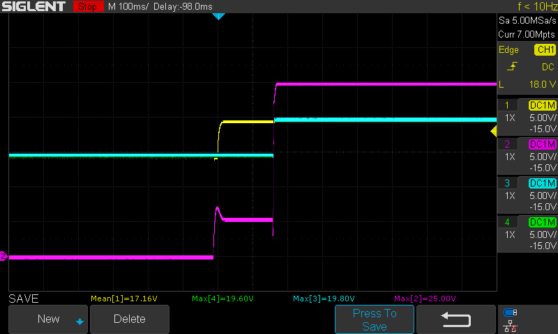
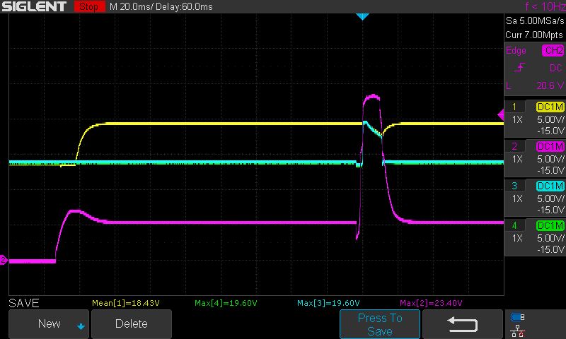
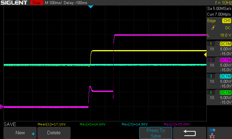
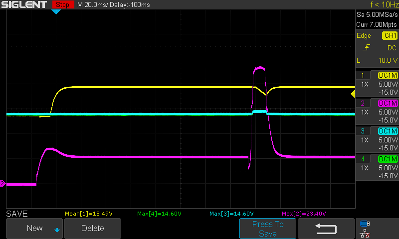
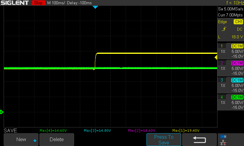
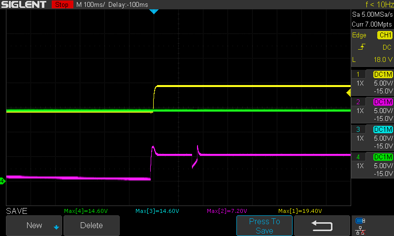
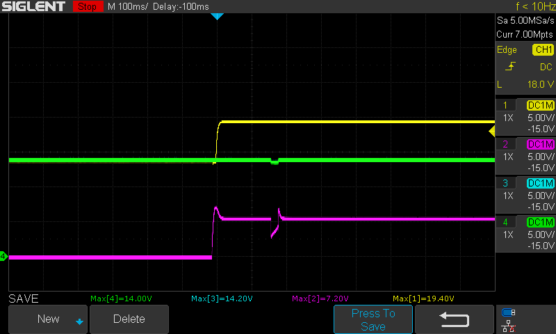
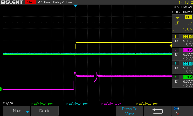
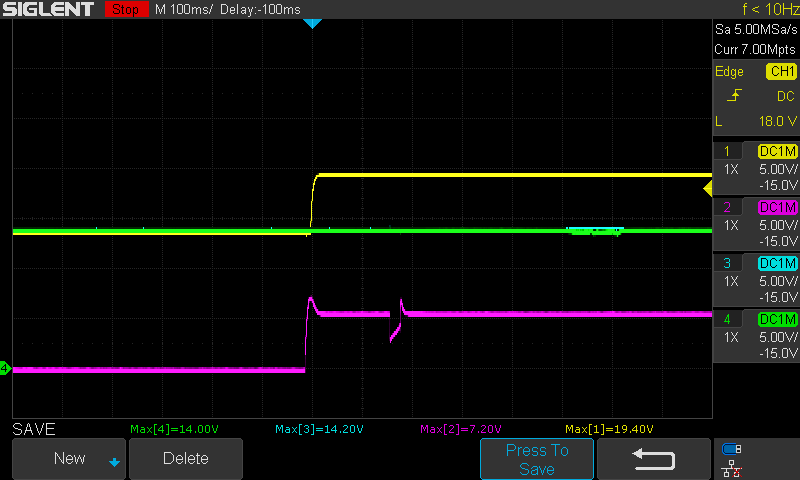
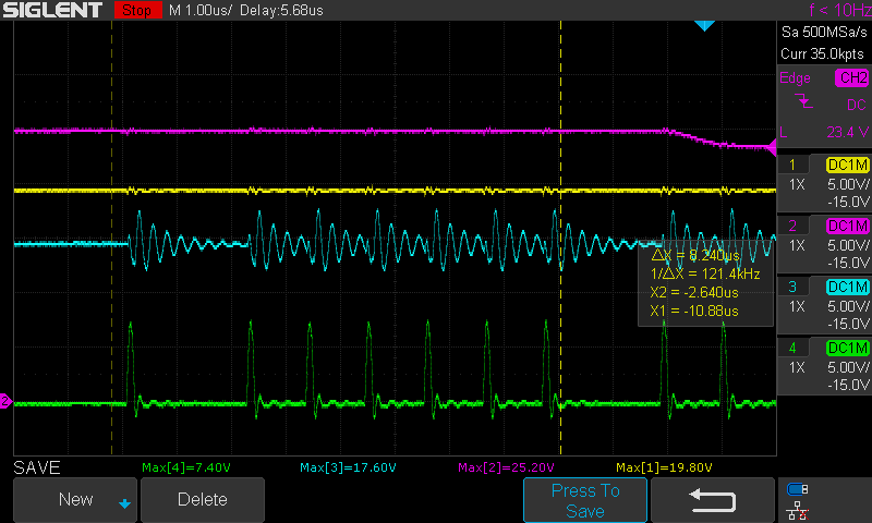
After investigating we saw that there is always a 14,4V on the H-FET gate driver (HIDRV).

The IC seems to have the behaviour of the Inductor Short, MOSFET Short Protection explained in the 8.4.18 section of the datasheet.

We tried disabling IFAULT_HI Comparator Threshold Adjust bit [8] to eliminate this theory, but it didn't do much.

I linked the schematic, any help would be appreciated.

Thank you

Olivier

  • Hey Olivier,

    Can you take the following scope capture?

    With the cells unconnected:

    Ch.1 - VCC pin voltage, trigger on the rising edge of this channel, offset by 15V and scale to 1V/div

    Ch.2 - SRN pin voltage, with same scale and offset and reference point as Ch.1 (this will let us see the differential voltage between VCC and SRN)

    Ch.3 - Input current

    Ch.4 - ACDRV

    With the cell connected:

    Same setup from above. Take a second waveform replacing Ch.4 showing the battery current.

    Regards,

    Joel H

  • Hi, Joel 

    Here are some scope captures for you to help identify the problem 

    Pic1 loaded 15 ohm
    CH1 VCC
    CH2 SRN
    CH3 Current input R19
    CH4 Current input R19


    Pic2 Loaded 15 ohm
    CH1 VCC
    CH2 ACDRV
    CH3 Current input R19
    CH4 Current input R19

    Pic3 unloaded
    CH1 VCC
    CH2 SRN
    CH3 Current input R19
    CH4 Current input R19


    Pic4 unloaded
    CH1 VCC
    CH2 ACDRV
    CH3 Current input R19
    CH4 Current input R19


    Pic5 unloaded with Batteries
    CH1 VCC
    CH2 SRN
    CH3 Current input R19
    CH4 Current input R19


    Pic6 Loaded 15 ohm with Batteries
    CH1 VCC
    CH2 SRN
    CH3 Current input R19
    CH4 Current input R19


    Pic7 unloaded with Batteries
    CH1 VCC
    CH2 ACDRV
    CH3 Current input R19
    CH4 Current input R19


    Pic8 Loaded 15 ohm with Batteries
    CH1 VCC
    CH2 ACDRV
    CH3 Current input R19
    CH4 Current input R19


    Pic9 unloaded with Batteries
    CH1 VCC
    CH2 ACDRV
    CH3 Current Battery R27
    CH4 Current Battery R27


    Pic10 Loaded 15 ohm with Batteries
    CH1 VCC
    CH2 ACDRV
    CH3 Current Battery R27
    CH4 Current Battery R27

    Thank you for your help 

    Olivier

  • I need to review these waveforms Olivier, 

    But just to confirm, I see the input current channels are measured in Volts, instead of Amps. Can you verify the scale and unit of measure?


    Regards,

    Joel H

  • We don't have a current probe on our scope so we took the voltage on each sides of R19 for the input current and R27 for the charge/battery

    As for the actual 19V Source, the current was set to 1Amp but never produced more than 0.01Amp when it was connected

    Thanks

    Olivier

  • Hey Olivier,

    Let's try two tests:

    1) Remove C17 and C18 and retry this test.

    2) On aother board, increase the C16 capacitor to 0.47uF and retry the test. 

    Regards,

    Joel H

  • Hi Joel here the results we have 

    Here are the same 10 graphs from the previous post without C17 and C18

    Pic1 loaded 15 ohm
    CH1 VCC
    CH2 SRN
    CH3 Current input R19
    CH4 Current input R19


    Pic2 Loaded 15 ohm
    CH1 VCC
    CH2 ACDRV
    CH3 Current input R19
    CH4 Current input R19


    Pic3 unloaded
    CH1 VCC
    CH2 SRN
    CH3 Current input R19
    CH4 Current input R19


    Pic4 unloaded
    CH1 VCC
    CH2 ACDRV
    CH3 Current input R19
    CH4 Current input R19


    Pic5 unloaded with Batteries
    CH1 VCC
    CH2 SRN
    CH3 Current input R19
    CH4 Current input R19


    Pic6 Loaded 15 ohm with Batteries
    CH1 VCC
    CH2 SRN
    CH3 Current input R19
    CH4 Current input R19


    Pic7 unloaded with Batteries
    CH1 VCC
    CH2 ACDRV
    CH3 Current input R19
    CH4 Current input R19


    Pic8 Loaded 15 ohm with Batteries
    CH1 VCC
    CH2 ACDRV
    CH3 Current input R19
    CH4 Current input R19


    Pic9 unloaded with Batteries
    CH1 VCC
    CH2 ACDRV
    CH3 Current Battery R27
    CH4 Current Battery R27


    Pic10 Loaded 15 ohm with Batteries
    CH1 VCC
    CH2 ACDRV
    CH3 Current Battery R27
    CH4 Current Battery R27

    We then did the test by changing C16 to 1uF because we didn't have a 0.47uF in hand 

    Pic1 loaded 15 ohm
    CH1 VCC
    CH2 SRN
    CH3 Current input R19
    CH4 Current input R19


    Pic2 Loaded 15 ohm
    CH1 VCC
    CH2 ACDRV
    CH3 Current input R19
    CH4 Current input R19


    Pic3 unloaded
    CH1 VCC
    CH2 SRN
    CH3 Current input R19
    CH4 Current input R19


    Pic4 unloaded
    CH1 VCC
    CH2 ACDRV
    CH3 Current input R19
    CH4 Current input R19


    Pic5 unloaded with Batteries
    CH1 VCC
    CH2 SRN
    CH3 Current input R19
    CH4 Current input R19


    Pic6 Loaded 15 ohm with Batteries
    CH1 VCC
    CH2 SRN
    CH3 Current input R19
    CH4 Current input R19


    Pic7 unloaded with Batteries
    CH1 VCC
    CH2 ACDRV
    CH3 Current input R19
    CH4 Current input R19


    Pic8 Loaded 15 ohm with Batteries
    CH1 VCC
    CH2 ACDRV
    CH3 Current input R19
    CH4 Current input R19


    Pic9 unloaded with Batteries
    CH1 VCC
    CH2 ACDRV
    CH3 Current Battery R27
    CH4 Current Battery R27


    Pic10 Loaded 15 ohm with Batteries
    CH1 VCC
    CH2 ACDRV
    CH3 Current Battery R27
    CH4 Current Battery R27

    We concluded the higher value at C16 was not helping the circuit and ACDRV was not able to drive with the 1uF cap 

    We also did a bit more searching on our own and we noticed something strange behavior at HIDRIVE 

    Once the input is turned on, the ACDRV works properly and the BATDRIVE goes down to let the Charger take control, but after 1-2 seconds the ACDRV goes back down 

    We probed the HIGH and LOW drive to see and theses are the results

    CH1  VDD

    CH2 ACDRV

    CH3 HIDRV

    CH4 LODRV

    We are not sure if this is normal and we can see that ACDRV starts to drop. We can`t see it in the picture but it drops to zero right after.

    We think the behavior we are seeing throughout theses tests is the 8.4.18 Inductor Short, MOSFET Short Protection because it describes exactly the response from the IC

    Hope all this informations is helpful

    Thanks 

    Olivier 

  • Hey Olivier,

    I was looking at the first set of waveforms and I am noticing that the VCC voltage seems to droop about 1V or so (5V/div scale), which means that VIN is also drooping with the same magnitude.

    You also mentioned you are using 19V input with 1A current limit. However, your load on pictures 3/4 and 6/8 are with a 15-Ohm load, which means the input current would be roughly 1.3A of peak current. Even though the DC current you saw was only 0.01A, you like did not see the peak current. It is very difficult to measure using the R19 capture you have taken because the differential voltage we are looking for between CH.3 and CH.4 is on the order of 10mV, and we are seeing a 5V/div scale.

    We can try several things:

    1) Confirm that the unloaded cases starts up. From pictures 1/2 and 5/7 of the original set of waveforms, you mention the system is unloaded, yet I still see the same characteristic glitch on VCC, which would assume the voltage is still drooping, perhaps from inrush current.

    2) Increase the input power rating, both voltage and current. So use something like 20V w/3A current limit.

    3) Either depopulate R28 (66.5kOhm) or increase its value to the same as R24 (430kOhm).

    From the second set of waveforms, it seems that either removing the delay elements make the issue worse with an increased current spike, and increase the 0.1uF delay element by 10x slows the response too much which may trigger some other logic. 

    I cannot explain the HIDRV waveform yet, but let's take a look at my actions for (1), (2), and (3) above. I would also suggest capturing the ACDET voltage (instead of the input or battery currents as they are not providing too much information right now). If you capture the ACDET voltage, please put a 2.4V offset, and set to 100-200mV/div vertical scale to capture any dip on ACDET. 

    Regards,

    Joel H

  • Hey Olivier,

    Any update on this?

    Regards,

    Joel H

  • We didn't have to time to look into it recently but we are planning on investigating on the 2019/11/20.

    We should be able to give you an update by the end of that day.

    Olivier 

  • We tried to increased the current and voltage to 20V/3A and nothing seemed to change from the charging perspective.

    With our unloaded setup this is what we see,

    We also checked the ACDET and without the modification mentioned at step 3  here are the results 

    After theses tests we don't think it is related to ACDET or the inrush current because the ACOK is acting correctly and no drop was seen on ACDET.

    We also tried to change the resistance at the ACDET to a 430kOhm, we don't understand why because the datasheet specifies that When the ACDET pin voltage is higher than 3.15V, it is considered as adapter over voltage. ACOK will be pulled low, and charge will be disabled. ACFET will be turned off to disconnect the high voltage adapter to system during ACOVP. BATFET will be turned on if turns on conditions are valid. See the System Power Selection section for details. We did try it and as expected the voltage at ACDET was around 9V and ACOK went down. 

    Thank you for your help 

  • We finally found the problem with the board, the LowSide transistor's ground pas was not soldered properly, but when testing the continuity the pressure applied was enough to bring back the connection hence why it took so long to figure it out.  

    Thank you for all the help 

    Olivier