Because of the holidays, TI E2E™ design support forum responses will be delayed from Dec. 25 through Jan. 2. Thank you for your patience.

This thread has been locked.

If you have a related question, please click the "Ask a related question" button in the top right corner. The newly created question will be automatically linked to this question.

TPS259824OEVM: Working Mode (Circuit Breaker or Current Limiter) at Special Moment

Part Number: TPS259824OEVM
Other Parts Discussed in Thread: TPS25982, TPS24751, TPS2493

Hello,

There are some interesting findings during our test on TPS259824OEVM. Please have a look at details in attached document. I'd appreciate if someone can provide any suggestion and explanation.

Thank you!

Michael

TI TPS259824OEVM Test Problem Report_20191030.pdf

  • Hi Michael,

    Thanks for reaching out!

    The device (either current limit type or circuit breaker type) always starts in current limit mode during

    • restart from overload fault
    • EN/ULVO reset with overload at the output
    • startup into overload at the output

    We will plan to add into datasheet with more clarity in the next revision of the datasheet.

    Best Regards,

    Rakesh

  • Hi Rakesh,

    Thanks for your prompt feedback.

    Now I know the reason of our test findings. Well, my understanding is: TPS259824O will only work as a "circuit breaker" when it is in a normal working condition (without any overload current). In most other situations (such as the three situations you mentioned), it actually works as a "current limiter". Is it correct?

    If it is correct, I am wondering if there is any way to work around that. It is highly undesirable that most of the time a "circuit breaker" doesn't operate as a "circuit breaker". Circuit breaker is chosen because we hope and assume it can always work as a circuit breaker (never works in current limit mode) in any condition. Does TI know if we can do any hardware modification to the device's peripheral circuit (or any other solution) to achieve our design expectation?

    Thank you!

    Michael

  • Hi Michael,

    Yes, Your understanding is correct.

    All these protection devices are controlled in current limit during high Vds mode for FET SOA protection. 

    Can you share your application use case, system block diagram and system specifications so that I can think of work around possibility.

    Thanks,

    Rakesh

  • Hi Rakesh,

    Please check attachment for application with eFuse and our design expectation.

    Please let me know if you need any more information.

    Thank you!

    Michael

    Application of TPS259827ONRGE_20191031.pdf

  • Hi Michael,

    Thanks for the block diagram and details.

    Are you trying to use TPS25982 device as constant current LED driver between the power supply and the LED load (where the LED load can vary depending on # of LEDs in series,  # of parallel strings, brightness etc) ?

    Do you have LED load and TPS25982 EVM to test. ? If yes - can you send test waveforms of starting with a soft overload condition.

    Best Regards,

    Rakesh

  • Hi Rakesh,

    We are not using TPS25982 device as a constant current LED driver. Our purpose is to use eFuse to replace conventional fuse because:  (1) we hope the fuse in our product can recover from fault without user intervention. (2) eFuse has many advantages in our application compared with PTC. (3) we also like to use its integrated current monitor function.

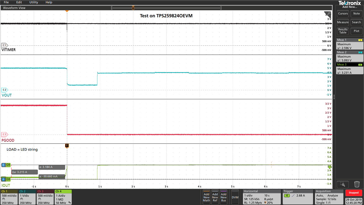
    The picture below shows a waveform in the test of TPS259824OEVM with our LED string. Major setups of EVM are: ILIM = 3A, ITIMER = 2ms, RETRY_DLY = 1s, NRETRY = Indefinite, VIN = 5V.

    At first, the LEDs worked in a low brightness pattern, so the output current to the string is low (less then 1A). Then, I made LEDs work in "full white" pattern so they consumed the highest current (which is several hundred mA high then ILIM) they could. The device was tripped by the high current and turned off its MOSFET almost immediately, which is exactly what we expected.

    After around 1s retry delay time, the device tried to restart. We expected that the device would be tripped immediately again due to the high load current. However, since the device restarted in current limit mode, it still output power to the load with a lower than specified output voltage. Some of the LEDs were turned on in "full white", some were turned on with a wrong color, some were not turned on at all.

    We hope the device can cut off the power output immediately every time it restarts if overload condition still exists at the output, since it is a circuit breaker. We hope the device will only output power when overload condition is removed. I am wondering if there is any thing we could do to make the device meet our design expectation.

    Thank you!

    Michael

  • Hi Michael,

    Thanks for the additional details. I got clear understanding on your expectation from the device for your application. In TPS25982 device, the circuit breaker timer does not active during restart in current limit mode, so the device continues to do current limit till it hits thermal shutdown due to power dissipation (Vin-Vout)*Ilim in current limit mode. 

    For your application the voltage and current levels are LOW and hence device is not entering into thermal shutdown.

    TPS24751 is ideal fit for your requirement. TPS24751 restarts in power limit or current limit (which ever is low) and the circuit breaker timer is always active as shown below.

    Best Regards,

    Rakesh

  • Hi Rakesh,

    Thanks for your recommendation.

    Just had a brief look at datasheet of TPS24751. Its recommended VCC range is from 2.5 to 18V, thought the max rating can be 30V. In our case, the input voltage can be as high as 24V. Did TI test this chip at any voltage above 18V? Will that affect its performance and functions?

    Thank you!

    Michael

  • Hi Michael,

    Sorry, I overlooked on the voltage spec..

    TPS2493 is an option. It has PG output, IMON feature and works between 9V to 80V input. Is it fine ?

    Best Regards,

    Rakesh

  • Hi Rakesh,

    Thanks for your recommendation.

    Maybe our application is a little bit special. The input voltage ranges from 5V to 24V, and its max current can reach 7.5A. I checked those "eFuse & hot swap controllers" products on TI website. It seems that TPS25982 is the only chip with internal MOSFET, which can meet our requirement of both voltage and current. Otherwise, hot-swap controller with external FET should be used. According to my search, UC3914 or UC2914 are probably our options. Just wondering if you have any other suggestions.

    Thank you!

    Michael

  • Hi Michael,

    Other option would be to monitor current output (IMON) of TPS25982 and then disable the device if the current is above certain threshold for a defined interval (couple of ms). This approach would need a micro-controller in the system.

    Thanks, Rakesh

  • Hi Rakesh,

    Thanks for your help and all these suggestions.

    We will do more investigation to see how to deal with this problem.

    Thank you!

    Michael